A voltage divider is one of the most widely used circuits in electronics. It allows you to obtain a lower voltage from a higher supply using resistors connected in series. Understanding the voltage division principle is essential for circuit design, sensor interfacing, transistor biasing, and signal conditioning.
This guide explains voltage divider equations, voltage divider formulas, the voltage division rule, and practical examples in a clear and structured way.
What Is a Voltage Divider?
A voltage divider is a simple yet widely used series resistor circuit that produces an output voltage equal to a fraction of the input voltage. The amount of voltage division depends entirely on the resistance values selected in the circuit. When resistors are connected in series, the supply voltage is distributed proportionally across them, which forms the foundation of the voltage division theorem. This principle makes it possible to derive multiple voltage levels from a single power source efficiently and predictably.
A voltage divider can operate with positive supplies such as +5V or +12V, negative supplies like −5V or −12V referenced to ground (0V), and even dual supplies such as ±5V or ±12V. Because voltage represents electrical potential difference between two points, this circuit is also referred to as a potential divider. By choosing appropriate resistor values and taking the output from the junction between them, a fixed and controlled portion of the input voltage can be obtained for use in different parts of an electronic system.
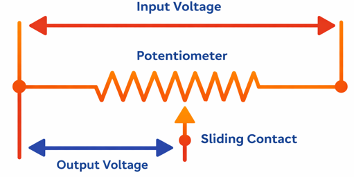
One of the most common examples of a voltage divider is the potentiometer, a variable resistor with a sliding wiper that allows the output voltage to be adjusted mechanically. While resistors are the most common components used, capacitors and inductors can also be connected in series to achieve voltage division in AC circuits. Simple, reliable, and cost-effective, the voltage divider remains a fundamental building block in electronic circuit design and signal conditioning applications.
Voltage Division Principle
The most basic and easy-to-understand form of a passive voltage divider consists of two resistors connected in series. This simple arrangement forms a resistor network where the applied input voltage is shared between the components.
According to the voltage division rule, in a series circuit the voltage drop across each resistor is proportional to its resistance relative to the total circuit resistance. Therefore, if two resistors are connected across a supply, the output voltage taken from one resistor depends on its share of the total resistance. By applying the Voltage Divider Rule, the exact voltage drop across each resistor can be calculated quickly and accurately.
The voltage division rule (also called the voltage division theorem) provides a quick way to calculate voltage drops in a series circuit without solving complex equations.
Important Conditions:
- Applicable only to series circuits
- Accurate when no significant load is connected to the output
- Output voltage is proportional to resistance
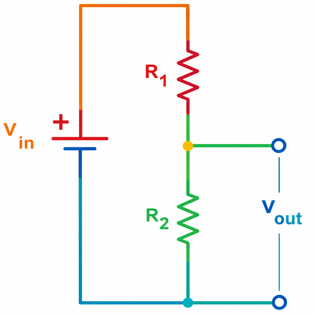
Voltage Divider Circuit
It consists of two resistors, R₁ and R₂, connected in series across an input voltage (Vin). The output voltage (Vout) is taken from the junction between the two resistors and the ground (bottom node).
Voltage Divider Equation Derivation
When a source voltage Vin is connected across two resistors in series, the same current flows through both components because there is only one path for current. By applying Kirchhoff’s Voltage Law (KVL), the total of the voltage drops across the resistors equals the input voltage. Using Ohm’s Law, each voltage drop can be expressed in terms of the common current I.
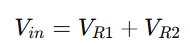
According to KVL:
Substituting Ohm’s Law (V=IR):
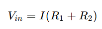
Factoring out the current:
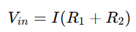
Solving for the current flowing through the series circuit:
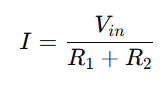
This gives the current in the voltage divider circuit in terms of the input voltage and total series resistance.
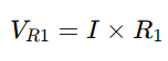
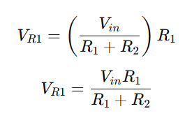
Voltage across R1
Substitute the value of I:
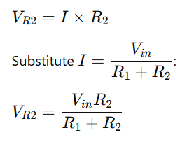
Voltage across R2
Voltage Divider Formula
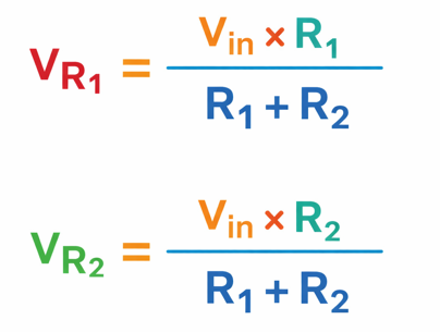
This is the standard equation for voltage divider calculations and represents the core of the voltage division rule.
General Voltage Division Formula (Multiple Resistors)
For multiple resistors connected in series:
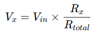
Where:
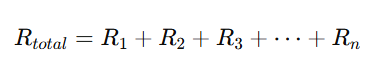
This generalized voltage divider equation is useful when analyzing larger resistor networks.
Rearranged Formula for Design Calculations
When designing a circuit to achieve a specific output voltage, the formula for voltage divider can be rearranged:
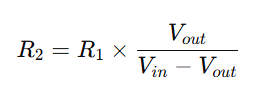
This form helps determine resistor values during circuit design.
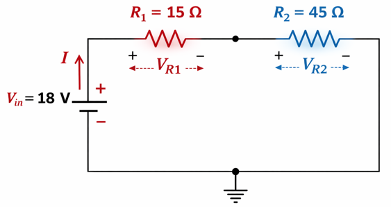
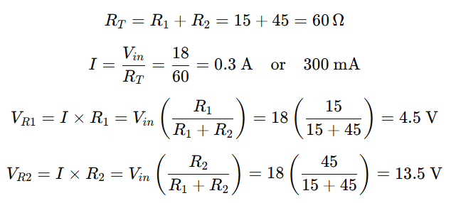
Example 1: Voltage Divider Rule
Determine the total current flowing in a circuit where a 15 Ω resistor is connected in series with a 45 Ω resistor. The combined circuit is supplied with 18 V DC. Also calculate the voltage drop across each resistor.
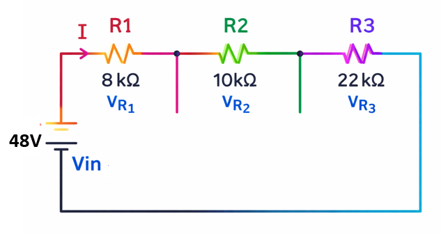
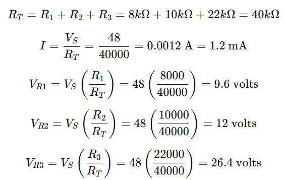
Example 2: Voltage Divider Rule
Three resistors with values of 8 kΩ, 10 kΩ, and 22 kΩ are connected in series across a 48 V DC supply. Determine the total circuit resistance, the current flowing through the circuit, and the voltage drop across each resistor.
Voltage Divider Potentiometer
A voltage divider potentiometer replaces fixed resistors with a variable resistor. It has three terminals and allows adjustable output voltage by moving a wiper along a resistive track.
Common Applications:
- Audio volume control
- Light dimmers
- Adjustable reference voltage
- Sensor calibration
Voltage Divider with Load (Loading Effect)
In practical circuits, a load resistor connected to the output changes the effective resistance.
If a load RL is connected across R2, the effective resistance becomes:
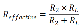
This reduces the output voltage. Therefore, loading effect must be considered in real-world designs.
Tapping Points in a Voltage Divider Network
A voltage divider network is formed when multiple resistors are connected in series across an input voltage (Vin). This arrangement allows different voltage levels to be obtained from various tapping points along the resistor chain. By placing taps at intermediate points—such as A, B, C, D, and E—you can access specific portions of the total input voltage without using multiple power sources.
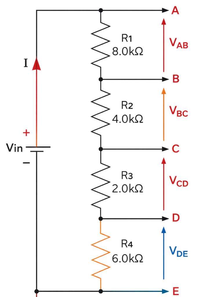
In a series voltage divider circuit, the total resistance is calculated by adding together all individual resistor values. For example, if the resistors combine to give a total resistance (RT) of 20 kΩ, this total resistance determines the amount of current flowing through the circuit according to Ohm’s Law (I = Vin / RT). Because the resistors are connected in series, the same current flows through each resistor in the network.
Each resistor produces a voltage drop proportional to its resistance value. These voltage drops can be represented as VR1 = VAB, VR2 = VBC, VR3 = VCD, and VR4 = VDE. The sum of all individual voltage drops is equal to the applied input voltage:
Vin = VR1 + VR2 + VR3 + VR4
This confirms the fundamental rule of series circuits: the total applied voltage is divided among the resistors.
The voltage at any tapping point is measured with respect to ground (0V), typically connected to the negative terminal of Vin. For example, the voltage at point D equals VDE, while the voltage at point C equals VCD + VDE. This means the voltage at any specific point is equal to the sum of the voltage drops between that point and ground.
By carefully selecting resistor values, a voltage divider network can provide multiple proportional output voltages from a single input supply. Since the negative terminal of Vin is grounded in this configuration, all tapping points provide positive voltage levels, making the circuit useful for voltage reference generation, biasing applications, and signal level control in electronic systems.
Positive and Negative Voltage Divider
In a basic voltage divider circuit, all output voltages are usually measured with respect to a single common ground (0V reference). This means every divided voltage is either above or equal to ground potential.
However, in some applications, it is necessary to obtain both positive and negative voltages from one power supply. In such cases, the circuit is arranged so that the reference point (ground) is placed between voltage levels, allowing outputs on one side to be positive and on the other side to be negative relative to that common reference.
A practical example is a computer power supply unit (PSU), which provides multiple voltage levels such as +3.3V, +5V, +12V, and −12V, all measured with respect to the same ground terminal. By selecting appropriate points in the divider network, both polarities can be obtained from a single source.
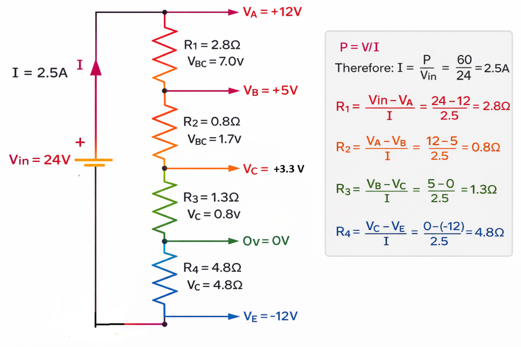
Example 3: Negative and Positive Voltage Divider
Apply Ohm’s Law to determine the resistor values R1, R2, R3, and R4 needed in a voltage divider circuit that generates output levels of −12V, +3.3V, +5V, and +12V. The circuit operates from a 24V DC supply, and the total power delivered to the unloaded voltage divider is 60 watts.
Your task is to calculate the appropriate resistance values so that each tapping point along the divider provides the specified voltage levels while maintaining the given total power and supply voltage conditions.
In this configuration, the ground (0V) reference point has been intentionally shifted to generate both positive and negative output voltages while keeping the voltage divider network connected across the same power supply. By relocating the zero-voltage reference, the circuit can deliver the required voltage levels without modifying the resistor arrangement. As a result, all four output voltages are measured relative to this common ground, placing point D at the specified −12V potential with respect to ground.
Series resistor circuits are widely used to form a voltage divider (also known as a potential divider) in electronic design. This simple yet effective circuit allows engineers to derive multiple voltage levels from a single supply source. By carefully selecting the resistance values, it is possible to obtain precise output voltages that are lower than the input or supply voltage. This makes voltage divider circuits essential in applications such as biasing transistors, setting reference voltages, and signal level adjustment.
While most basic voltage divider circuits use resistors with a DC power supply, the same principle can be applied using capacitors (C) and inductors (L) in AC circuits. Unlike resistors, capacitors and inductors are reactive components, meaning their opposition to current—called reactance—depends on the frequency of the applied sinusoidal AC signal. This property allows reactive voltage divider networks to be used in filters, frequency-selective circuits, and signal processing systems where frequency response is important.
Capacitive Voltage Divider in AC Circuits
A capacitive voltage divider is an AC circuit configuration that uses two or more capacitors connected in series across a sinusoidal voltage source to produce a reduced output voltage. Unlike resistive voltage dividers, which operate with both AC and DC supplies, capacitive dividers function only with alternating current because they rely on capacitive reactance (XC). This reactance depends on both the frequency of the supply and the capacitance value, making the circuit frequency-sensitive.
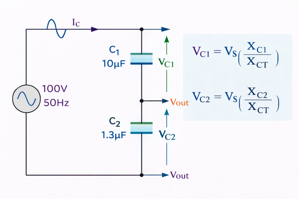
In a series capacitive divider, the voltage across each capacitor is determined by its reactance. Since reactance is inversely proportional to capacitance, a smaller capacitor produces a larger voltage drop. The total of all individual voltage drops equals the applied supply voltage, similar to a resistive series circuit.
Capacitive voltage dividers are widely used in high-frequency electronics, signal coupling, voltage measurement, filtering applications, and modern touchscreen and display technologies.
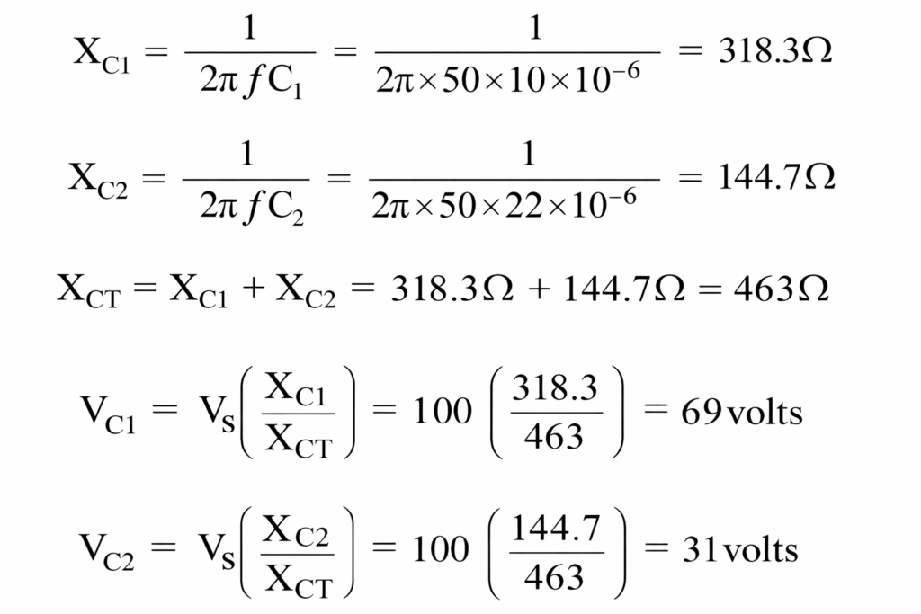
Example 4: Capacitive Voltage Divider
Inductive Voltage Divider in AC Circuits
An inductive voltage divider is an AC circuit that produces voltage drops across inductors connected in series to a common alternating supply. It may consist of two separate coils connected in series or a single coil with tapping points, such as in an autotransformer. In these configurations, the output voltage is taken from a portion of the winding, making inductive dividers widely used in power control and variable voltage applications.
Inductive voltage dividers operate only with sinusoidal AC supplies. When connected to DC or very low-frequency signals (approaching 0 Hz), inductors behave like short circuits because their reactance becomes nearly zero. Therefore, meaningful voltage division occurs only when frequency is present. The voltage distribution depends on inductive reactance (XL), which determines how much each inductor opposes AC current.
Inductive reactance (XL), measured in ohms, is directly proportional to both the supply frequency and the inductance value. As frequency increases, reactance increases, resulting in a greater voltage drop across the inductor. This relationship is expressed as: XL=2πfL, where f is the frequency in hertz and L is the inductance in henrys.
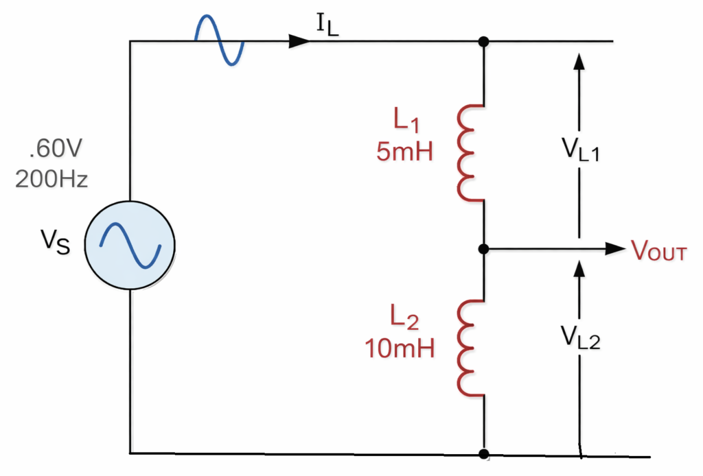
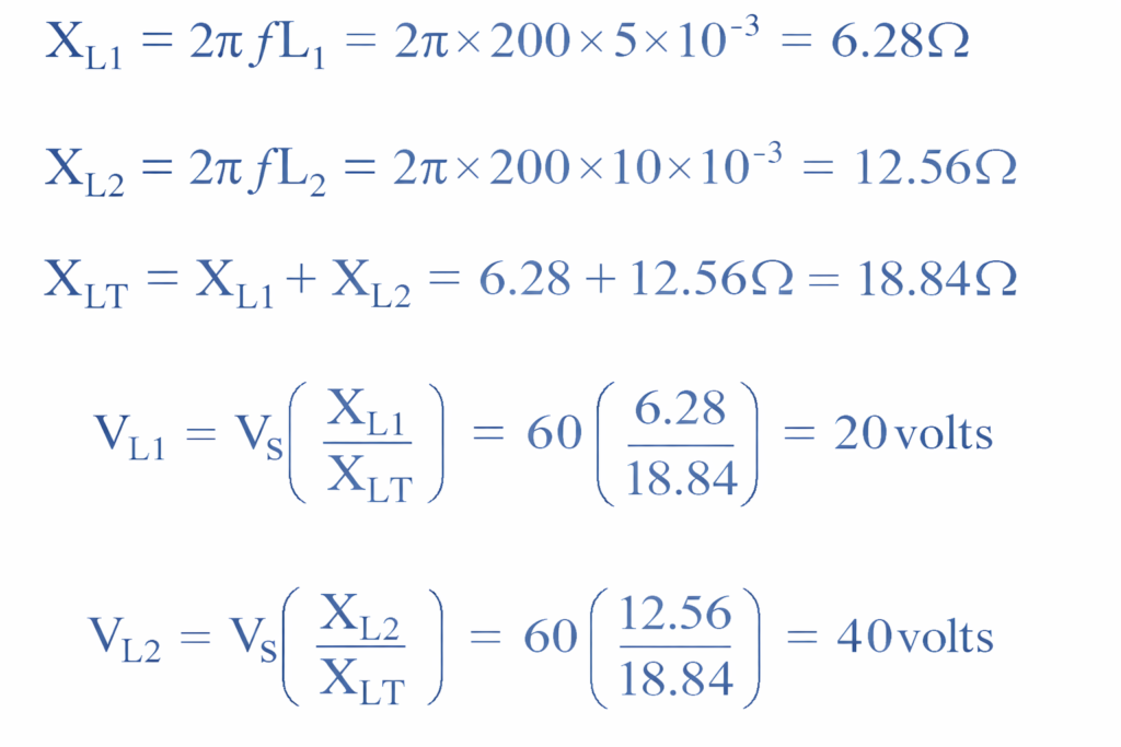
Example 5: Inductive Voltage Divider
Using two inductors rated at 5 mH and 10 mH connected in series, we can determine the RMS voltage drop across each inductor by first calculating their inductive reactance. When the circuit is supplied with a 60V, 200Hz RMS AC source, the voltage division depends on the reactance (XL) of each inductor at that frequency. After finding the reactance values using the formula XL=2πfL, the individual RMS voltage drops across each inductor can be calculated in proportion to their reactance within the series circuit.
Applications of Voltage Divider
Voltage dividers are used in:
- Sensor circuits (thermistors, LDRs)
- Transistor biasing networks
- Signal level scaling
- Analog-to-digital converter input protection
- Reference voltage generation
Advantages
- Simple and inexpensive
- Easy to analyze using voltage divider equations
- No active components required
Limitations
- Not efficient for high-current loads
- Output voltage varies with load
- Power dissipated in resistors
Conclusion
The voltage divider is a foundational concept in electronics built on the voltage division principle. By mastering voltage divider formulas and understanding the voltage division rule, you can design reliable resistor networks for a wide range of applications.
From simple voltage scaling to adjustable voltage divider potentiometer circuits, this technique remains one of the most important tools in circuit design.
Read Next: