Capacitors are one of the most essential components in electrical and electronic circuits. Whether you’re designing power supplies, filters, or timing circuits, understanding capacitors in series is critical. In this comprehensive guide, we’ll take a deep dive into the series connection of capacitor, explore formulas, derivations, voltage behavior, and practical examples.
What Are Capacitors in Series?
When two or more capacitors are connected end-to-end in a single path, they form a series of capacitor configuration. In this arrangement, the same current flows through each capacitor because there is only one path for charge flow.
Key Concept:
- Same current flows through all capacitors
- Same charge is stored on each capacitor
- Voltage divides across capacitors
This is fundamentally different from capacitors in parallel, where voltage remains constant and capacitance adds directly.
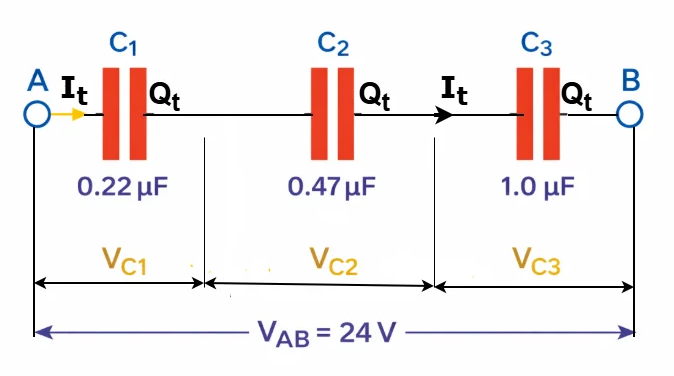
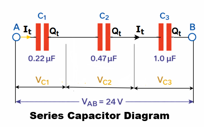
Series Capacitor Diagram
A simple series capacitor diagram looks like this:
In a parallel circuit, the total capacitance CT is simply the sum of all individual capacitors. However, when capacitors are connected in series, the method of finding the total (or equivalent) capacitance is different.
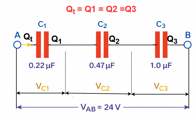
In a series circuit, the right-hand plate of the first capacitor, C₁, is connected to the left-hand plate of the second capacitor, C₂. Similarly, the right-hand plate of C₂ is connected to the left-hand plate of the third capacitor, C₃, forming a continuous chain. Due to this series arrangement in a DC circuit, the middle capacitor, C₂, does not interact directly with the external circuit and behaves as if it is isolated between C₁ and C₃.
As a result, the overall effect is similar to having a reduced plate area—essentially limited by the smallest capacitor in the series. Consequently, the voltage across each capacitor is not the same and varies according to the value of its capacitance.
Voltage and Charge Distribution in Series Capacitors
In a capacitor in series, the charge on each capacitor is the same:
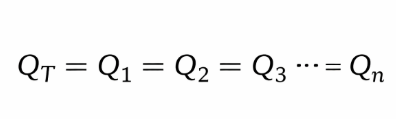
where QT represents the total charge stored in the entire circuit, and Q1 through Qn denote the charges on each individual capacitor.
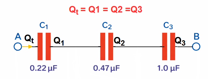
To understand why each capacitor in a series stores the same amount of charge, imagine that all the capacitors are initially uncharged. When a voltage is applied across the series combination, the same current flows through every capacitor in the chain, causing charge to move.
Electrons are transferred from one plate to another across each capacitor. The charge that appears on a plate of one capacitor originates from the plate of its neighboring capacitor. In other words, charge carriers (electrons) are simply passed along through the entire series path. This continuous movement ensures that every capacitor ends up holding an equal amount of charge.
Now Let us understand the voltage distribution in series connected capacitors.
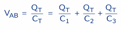
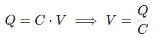
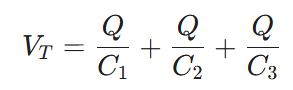
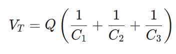
By applying Kirchhoff’s Voltage Law (KVL) to the given circuit, the following relation is obtained:
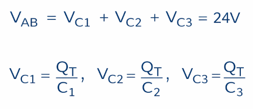
Since Q=C×V, we can rearrange it as V=Q/C. Substituting Q/C for each capacitor voltage VC in the above KVL equation gives:
For resistors connected in series, the sum of the voltage drops across each component equals the applied voltage VS, according to Kirchhoff’s Voltage Law. This same principle also applies to capacitors connected in series.
When capacitors are connected in series, each one exhibits capacitive reactance, which behaves like an impedance that depends on the supply frequency. This reactance causes a voltage drop across each capacitor, making the series combination function as a capacitive voltage divider.
As a result, the same voltage divider principle used for resistors can also be applied to determine the voltage across each capacitor in a two-capacitor series arrangement. Thus:

Where: CX represents the capacitance of the specific capacitor being considered, VS is the total applied voltage across the entire series combination, and VCX is the voltage developed across that particular capacitor.
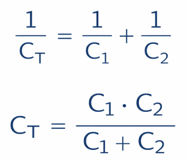
Series Capacitors Formula
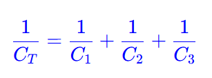
The most important concept is the capacitors in series formula, which calculates total capacitance.
For capacitors connected in series, you don’t add their capacitance values directly. Instead, you add the reciprocals of each capacitor, similar to how resistors combine in parallel. The total capacitance is then found by taking the reciprocal of this sum of reciprocals.
A crucial thing to keep in mind when dealing with capacitors connected in series is that the overall capacitance of the circuit (CT) is always smaller than the capacitance of the smallest individual capacitor in the chain.
For example, if three capacitors of 6μF, 3μF, and 2μF are connected in series, the total capacitance will be less than 2μF, which is the smallest value. This happens because the series arrangement effectively reduces the ability of the circuit to store charge.
Special Case: Two Capacitors in Series
The capacitors in series calculation is based on the reciprocal formula, which works for any number of capacitors connected in series. However, when only two capacitors are involved, a simpler and faster formula can be applied, expressed as:
If both capacitors are equal:
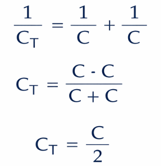
We can conclude that only when the two capacitors connected in series are identical does the total capacitance, CT, become exactly half of a single capacitor’s value, i.e., C/2.
Capacitor in Series Formula Derivation (Proof)
Let’s derive the capacitor in series equation step by step.
Step 1: Apply Kirchhoff’s Voltage Law (KVL)

Step 2: Use relation
Substitute into KVL:
Step 3: Factor out Q
Step 4: Define total capacitance
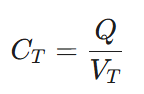
Rearranging gives:
This completes the capacitor in series proof.
Capacitors in Series Example No1
Three capacitors 2µF, 4µF and 6µF are connected in the series. Find the equivalent capacitance.
- C1 = 2µF
- C2 = 4µF
- C3 = 6µF
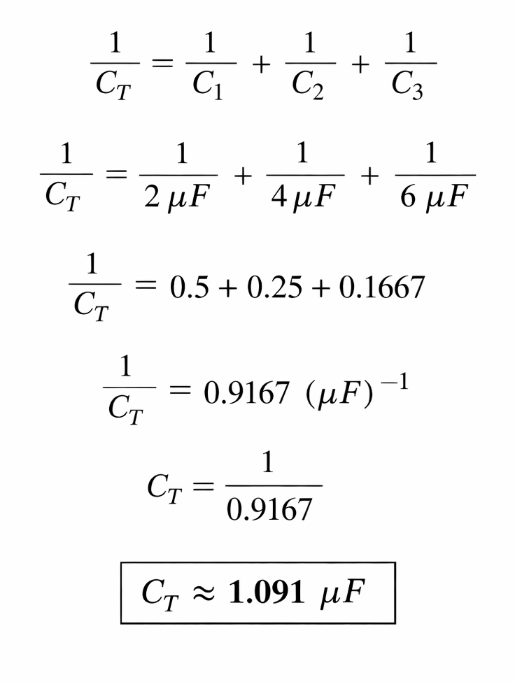
Quick Check: In a series circuit, the total capacitance (CT) must be smaller than the smallest individual capacitor. Since combining capacitors in series is 1.09 µF which smaller than 2µF, the result is logically consistent.
Capacitors in Series Example No 2
Determine the equivalent capacitance and the RMS voltage across each capacitor for the following series combinations when connected to a 12 V AC source:
a) Two identical capacitors, each having a capacitance of 68 nF
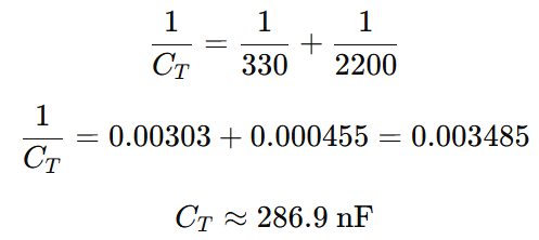
b) A series combination of two capacitors with values 330 nF and 2.2 μF
a) Total Equal Capacitance,
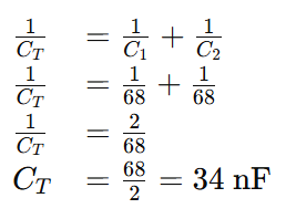
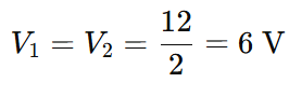
Voltage drop across the two identical 68nF capacitors,
- Supply = 12 V (rms)
- Equal capacitors → equal voltage division
b) Total Unequal Capacitance,
Voltage drop across the two non-identical capacitors
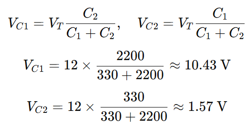
Because Kirchhoff’s voltage law applies to all series circuits, the sum of the voltage drops across the individual capacitors equals the total supply voltage, VT. For example: VC1+VC2=10.43+1.57=12 V.
It is important to note that when the capacitors in a series circuit are identical, such as the 68 nF each example above, the supply voltage is split equally among them. This occurs because each capacitor accumulates the same charge, Q=C×V=0.816 μC, resulting in each capacitor receiving half of the total applied voltage, VT. For circuits with more than two identical capacitors, the voltage divides proportionally.
In contrast, when the series capacitors have different values, the larger capacitor reaches a lower voltage while the smaller capacitor attains a higher voltage. In our unequal example with C1=330 nF and C2=2200 nF, the voltages were calculated as VC1=10.43 V and VC2=1.57 V. This difference ensures that both capacitors hold the same charge on their plates, maintaining electrical consistency throughout the series arrangement.
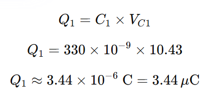
Charge on C1
Charge on C2

It is important to understand that the ratio of voltage drops across capacitors connected in series remains constant, regardless of the supply frequency. This is because the capacitive reactance XC of each capacitor changes proportionally with frequency.
In our example with C1=330 nF and C2=2.2μF, the voltage drops of approximately 10.43 V and 1.57 V will stay the same even if the supply frequency is increased from 100 Hz to 100 kHz.
Although the voltage across each capacitor depends on its capacitance, the charge on each capacitor remains equal. This occurs because the same current flows through all components in a series circuit, delivering the same quantity of electrons to each capacitor.
In other words, when the charge Q is constant, a smaller capacitance results in a higher voltage drop across its plates, as the charge is large relative to its capacitance. Conversely, a larger capacitor has a lower voltage drop, because the same charge corresponds to a smaller voltage relative to its capacitance.
Capacitors Series vs Capacitors in Parallel
| Feature | Capacitors in Series | Capacitors in Parallel |
|---|---|---|
| Charge | Same | Different |
| Voltage | Divides | Same |
| Capacitance | Decreases | Increases |
| Formula | Reciprocal sum | Direct sum |
Capacitors in Series on Breadboard

When building capacitors in series on breadboard:
- Connect one leg of capacitor to another
- Ensure polarity (for electrolytic capacitors)
- Measure voltage across each capacitor carefully
Practical Applications of Capacitors Series
1. Voltage Division
• Used in circuits requiring specific voltage levels
• Ensures voltage is distributed across components in a controlled manner
• Common in measurement circuits and sensor interfaces
2. High Voltage Applications
• Series capacitors increase overall voltage rating
• Allows use of lower-rated capacitors in high-voltage systems
• Widely used in power transmission and high-voltage DC systems
3. Signal Coupling
• Used in filters and AC circuits
• Blocks DC while allowing AC signals to pass
• Helps in reducing noise and improving signal quality in communication circuits
4. Power Electronics
• Common in inverters and converters
• Used for energy storage and voltage smoothing
• Helps in improving efficiency and stability of power systems
5. Energy Storage Optimization
• Series connection adjusts total capacitance to required levels
• Useful where lower capacitance with higher voltage tolerance is needed
6. Tuning and Resonant Circuits
• Used in LC circuits for tuning frequency
• Applied in radios, transmitters, and oscillators
Advantages of Capacitor in Series
- Increases voltage handling capacity
- Useful for voltage division
- Reduces overall capacitance
Disadvantages
- Lower total capacitance
- Unequal voltage distribution
- Risk of capacitor damage if not balanced
Summary of Capacitors in Series
- Capacitors in series share the same charge
- Voltage divides across each capacitor
- Total capacitance decreases
- Use reciprocal formula for calculation
- Smaller capacitors carry higher voltage
Conclusion
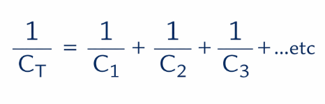
Then to summarise, the total or equivalent capacitance, Cₜ, of a series circuit is the reciprocal of the sum of the reciprocals of all the individual capacitances added together:1 / Cₜ = 1 / C₁ + 1 / C₂ + 1 / C₃ …
For capacitors connected in series, the same charging current flows through each capacitor, so iₜ = i₁ = i₂ = i₃ …. As a result, all capacitors in series carry the same amount of charge, Q, across their plates.
Since the charge, Q, is equal and constant, the voltage drop across each capacitor depends only on its capacitance, according to: V = Q ÷ C
This means that a smaller capacitance produces a larger voltage drop, while a larger capacitance produces a smaller voltage drop.
Understanding capacitors in series and series capacitor circuits formula is essential for anyone working in electronics. From theoretical derivation to practical applications, mastering the series capacitor formula helps you design efficient and safe circuits.
Whether you’re using a capacitor in series calculator, building circuits on a breadboard, or solving exam problems, the principles remain the same.
Read Next: