Resistors can be connected in different ways to meet the requirements of an electrical circuit. The two most common configurations are resistors in series and resistors in parallel, although many practical circuits use a combination of both. When resistors are connected in a series connection, they form a single current path, and the circuit can be simplified by replacing them with one equivalent resistor whose value is equal to the sum of the individual resistances.
A resistor is one of the most widely used passive components in electrical and electronic circuits. Besides limiting current, it is used to control voltage, divide voltage levels, protect sensitive components, and establish reference voltages in various applications. By selecting suitable resistor values, designers can achieve the desired current flow and voltage distribution within a circuit.
Whether a circuit contains two resistors in series or a complex network of many resistors, its behavior can be analyzed using fundamental electrical principles. The equivalent resistance, current, and voltage across resistors in series can be determined using Ohm’s Law and Kirchhoff’s Circuit Laws, making circuit analysis simpler and more systematic.
This article explains the working principle of resistors in series, the resistors in series formula, how to calculate equivalent resistance, determine the voltage across a resistor in series, and solve practical examples using simple step-by-step calculations.
Resistors in Series
A resistors in series circuit is formed by joining two or more resistors so that they behave as a single resistive path between the power source and the load. Instead of acting independently, each resistor contributes to the overall resistance of the circuit. As additional resistors are connected in a series connection, the equivalent resistance increases, affecting both the circuit current and the voltage distribution.
Because of these characteristics, series resistors are widely used whenever a circuit requires current limiting, voltage division, or a specific resistance value that cannot be obtained with a single resistor. Understanding how resistance, current, and the voltage across a resistor in series are related is essential for circuit design, troubleshooting, and electrical calculations.
Characteristics of Resistors in Series
A circuit containing in series resistors has several important characteristics.
- Only one path is available for current.
- Current remains the same through all resistors.
- Voltage is divided across each resistor.
- Total resistance increases as more resistors are added.
- If one resistor becomes open, the entire circuit stops working.
These properties make series resistors useful in many electrical applications.
Series Resistor Circuit
In a series connection, the output terminal of one resistor is connected to the input terminal of the next resistor. The circuit below illustrates three resistors connected in a series configuration
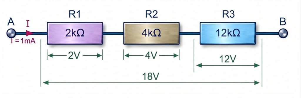
Current flows through R1, then R2, and finally R3 before returning to the source.
Since the resistors are connected in a series connection, electric current has only one continuous path to follow. As a result, the current remains identical through every resistor in the circuit. The equivalent or total resistance (REQ) is obtained by adding the resistance of each individual resistor,
Using the resistor values from the example above, the equivalent resistance is calculated by adding the individual resistor values, as shown below:
The three resistors in the above example can be replaced with a single equivalent resistor having a resistance of 18 kΩ. From the perspective of the power source, both circuits behave identically because they produce the same current and voltage distribution.
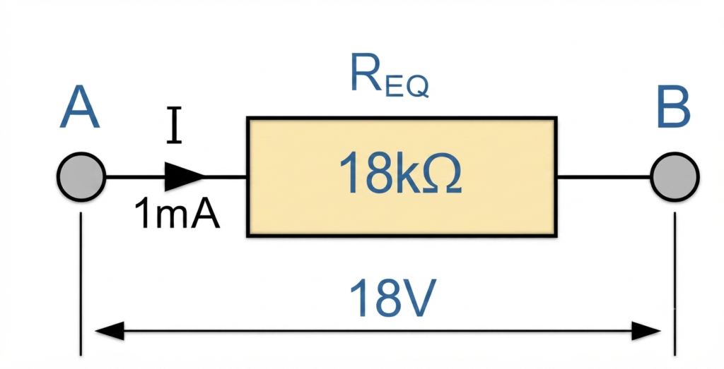
The same principle applies regardless of the number of resistors in the circuit. Whether there are three, four, five, or more resistors in series, the equivalent resistance is obtained by adding the resistance of each individual resistor. Therefore, every additional resistor connected in a series connection increases the total circuit resistance.
The combined resistance of all the series-connected resistors is known as the equivalent resistance (REQ). It represents the value of a single resistor that can replace the entire resistor network without changing the electrical behavior of the circuit.
Resistors in Series Formula
The general formula for calculating the equivalent resistance of series resistors is:
Where:
- RT = Total equivalent resistance
- R1, R2, R3…Rn = Individual resistor values
The equivalent resistance (RT) produces the same electrical effect as the complete series resistor network. In other words, replacing all the individual resistors with a single resistor of value RT does not change the current or the overall behavior of the circuit because RT is simply the sum of all the individual resistances.
Two Resistors in Series
The simplest series circuit contains two resistors in series.
When resistors in series have identical resistance values, calculating the equivalent resistance becomes very simple. The total resistance (RT) is obtained by multiplying the resistance of one resistor by the total number of resistors connected in the series connection.
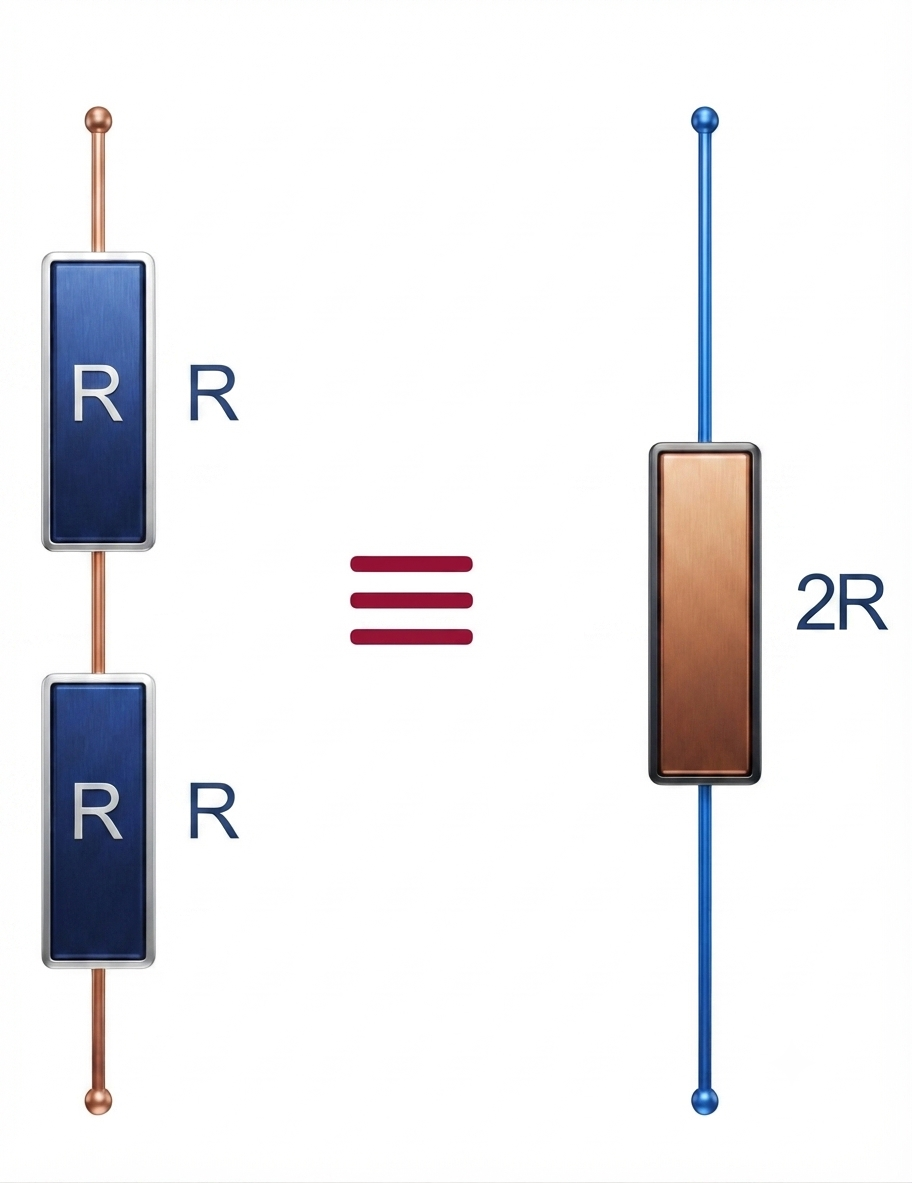
For example, if two resistors in series each have a resistance of R, the equivalent resistance is 2R. Likewise, three identical series resistors produce an equivalent resistance of 3R, four identical resistors result in 4R, and so on.
In general, if n identical resistors, each having a resistance R, are connected in series, the equivalent resistance is:
When resistors in series have different resistance values, the equivalent resistance is calculated by adding the resistance of each resistor. This rule applies regardless of whether the circuit contains two resistors in series or several resistors connected in the same series connection.
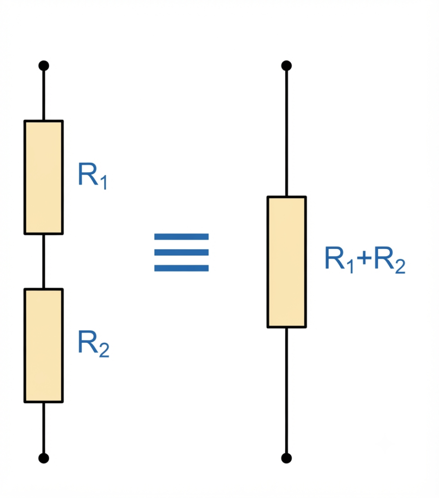
For example, if two series resistors have resistance values of R₁ and R₂, the total resistance is:
A simple way to verify your calculations for resistors in series is to compare the equivalent resistance with the individual resistor values. In a series connection, the total resistance (RT) is always greater than the resistance of the largest single resistor because each resistor adds to the overall resistance of the circuit.
For example, if three series resistors have values of 2 kΩ, 4 kΩ, and 12 kΩ, the equivalent resistance is 18 kΩ. Since 18 kΩ is greater than the largest individual resistor (12 kΩ), the calculation is correct. If your calculated total resistance is smaller than the largest resistor in the series circuit, it indicates that an error has been made in the calculation.
Current Through Series Resistors
In a series connection, every resistor carries the same current because the circuit provides only one continuous path for the flow of electric charge. However, the voltage drop across each resistor is not necessarily the same. Instead, it depends on the resistance value of that resistor, with higher resistance producing a larger voltage drop.
When resistors in series are connected one after another, electric current cannot split into multiple paths. As a result, the current leaving the power source passes through each resistor in sequence before returning to the source. This means the current remains constant throughout the entire series circuit, regardless of the number of series resistors connected.
The current flowing through resistors in series remains identical.
Example:
Supply Voltage = 24 V
Total Resistance = 12 Ω
Current:
Every resistor carries 2 A.
Voltage Across a Resistor in Series
Unlike current, which remains constant throughout a series connection, the voltage across resistors in series is divided among the individual resistors. The amount of voltage dropped across each resistor depends on its resistance value. A resistor with higher resistance experiences a larger voltage drop, while a resistor with lower resistance has a smaller voltage drop.
According to Kirchhoff’s Voltage Law (KVL), the sum of all individual voltage drops in a series circuit is always equal to the applied supply voltage. Therefore,
Example: Consider a series circuit supplied with 18 V and carrying a current of 1 mA. The resistor values are:
- R₁ = 2 kΩ
- R₂ = 4 kΩ
- R₃ = 12 kΩ
Using Ohm’s Law (V = IR), the voltage across each resistor in series is calculated as follows:
For R₁:
Volatge drop across R₂:
For R₃:
Adding the individual voltage drops gives:
The total equals the supply voltage, confirming that the calculations are correct.
Since the supply voltage is shared among the series resistors, a series connection naturally acts as a voltage divider. The voltage across each resistor is proportional to its resistance value, making this configuration ideal for generating different voltage levels from a single power source. Voltage divider circuits are widely used in electronic equipment, sensor interfaces, analog circuits, and measurement systems.
By applying Ohm’s Law together with Kirchhoff’s Voltage Law, you can easily determine the current, resistance, or voltage across a resistor in series. Another advantage of a series circuit is that changing the physical order of the resistors does not affect the equivalent resistance, circuit current, or the voltage drop across each resistor, provided the resistor values remain unchanged.
Resistors in Series Example No1
Using Ohm’s Law, determine the equivalent resistance, circuit current, voltage across each resistor in series, and the power dissipated by each resistor for the series circuit shown below.
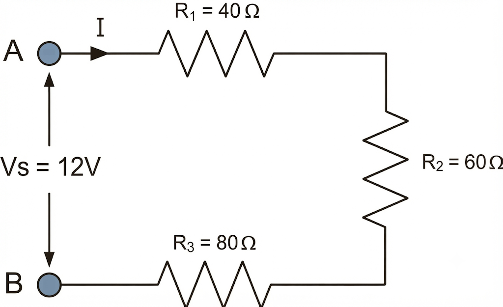
The required values can be calculated by applying Ohm’s Law and the formulas for resistors in series. For clarity and easier comparison, the calculated results are summarized in the table below.
| Component | Resistance | Current | Voltage | Power |
|---|---|---|---|---|
| R1 | 40 Ω | 66.67 mA | 2.67 V | 0.18 W |
| R2 | 60 Ω | 66.67 mA | 4.00 V | 0.27 W |
| R3 | 80 Ω | 66.67 mA | 5.33 V | 0.36 W |
| RT / Total | 180 Ω | 66.67 mA | 12.00 V | 0.80 W |
From the above calculations, the equivalent resistance is RT = 180 Ω, the circuit current is IT = 66.67 mA, the supply voltage is VS = 12 V, and the total power dissipated by the series circuit is PT = 0.80 W.
Voltage Divider Circuit Using Resistors in Series
One of the most useful applications of resistors in series is the voltage divider circuit. In a series connection, the source voltage is shared among the individual resistors instead of appearing entirely across a single resistor. The voltage drop across each resistor depends on its resistance value, allowing multiple output voltages to be obtained from a single DC supply.
This principle makes a series resistor network an effective and inexpensive way to generate different voltage levels for electronic circuits. Since the same current flows through every resistor in a series connection, the voltage across each resistor is directly proportional to its resistance. As a result, a resistor with a higher resistance produces a larger voltage drop, while a resistor with a lower resistance produces a smaller voltage drop.
For example, a 18V supply connected to three resistors in series can produce voltage drops of 2 V, 4 V, and 12 V, depending on the resistor values. The sum of these individual voltage drops is always equal to the supply voltage, in accordance with Kirchhoff’s Voltage Law (KVL).
The operation of a voltage divider is based on the Voltage Divider Rule, which provides a simple method for calculating the voltage across a resistor in series without determining the voltage drop across every resistor individually. Because of its simplicity and reliability, the voltage divider circuit is widely used in sensor interfaces, analog circuits, reference voltage generation, signal conditioning, and electronic control systems.
Voltage Divider Network
The figure below illustrates a typical voltage divider circuit using resistors in series.
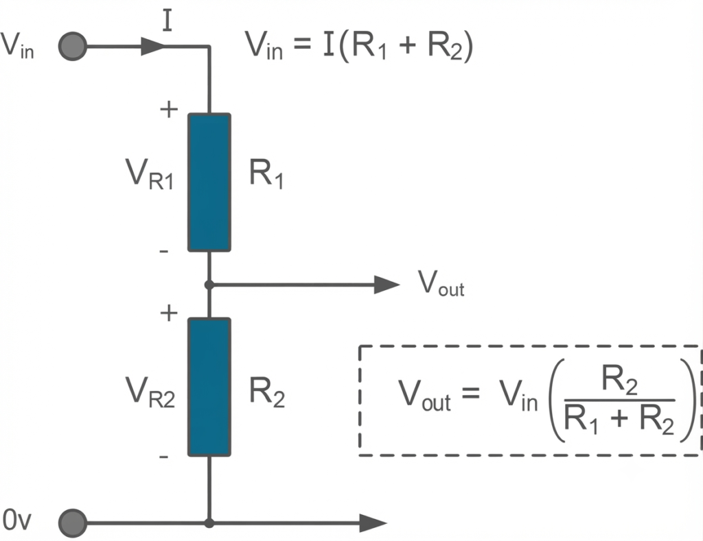
A basic voltage divider circuit uses two resistors in series, R₁ and R₂, connected across an input supply voltage (Vin). The output voltage (Vout) is obtained from the junction of the two resistors. Its value depends on the ratio of the resistor values rather than their individual resistance alone, making it easy to obtain a desired voltage from a fixed supply.
The same concept can be extended by connecting resistors in series. As additional resistors are added, the source voltage is divided into multiple voltage drops across the resistor network. Each voltage across a resistor in series is proportional to its resistance, allowing several output voltage levels to be derived from a single input voltage. This principle is widely used in electronic circuits for voltage scaling, reference voltage generation, sensor interfacing, and signal conditioning.
The Voltage Divider Rule is not limited to circuits containing only two resistors. It can also be applied to three or more resistors in series to determine the voltage across each resistor. By knowing the supply voltage and the resistance values, the voltage drop across every resistor in the series connection can be calculated easily. The following circuit illustrates this concept.
The voltage divider circuit shown below consists of four resistors in series connected across a common voltage source. To determine the voltage across the section between points A and B, apply the Voltage Divider Rule using the equivalent resistance of the required portion of the circuit, as shown below:
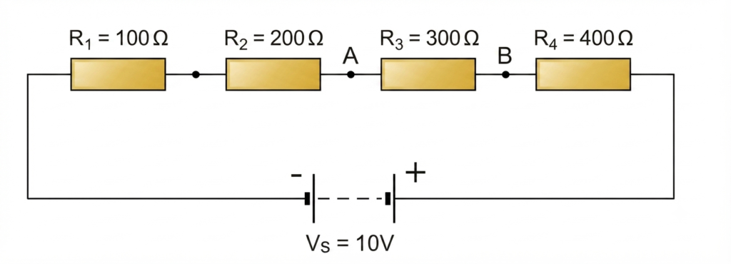
The Voltage Divider Rule can also be used to determine the voltage across a combination of adjacent resistors in series. Instead of calculating the voltage drop across a single resistor, simply add the resistance values of the required resistors and use their combined resistance in the numerator of the voltage divider formula. For example, if the required output voltage is taken across R₂ and R₃, the voltage across these two resistors is the sum of their individual voltage drops.
In the previous example, the resistor values are selected so that the voltage distribution is easy to understand. Since the total circuit resistance is 1000 Ω, each resistor receives a share of the supply voltage proportional to its resistance. As a result, R₁ (100 Ω) drops 10% of the source voltage, R₂ (200 Ω) drops 20%, R₃ (300 Ω) drops 30%, and R₄ (400 Ω) drops 40%. The sum of these voltage drops is always equal to the applied supply voltage, satisfying Kirchhoff’s Voltage Law (KVL).
Effect of Load on a Voltage Divider Circuit
In practice, a voltage divider circuit is often used to obtain a lower voltage from a higher DC supply. For example, a 18 V source can be divided to produce 9 V by connecting two equal resistors in series. While this arrangement works perfectly under no-load conditions, the output voltage changes when a load is connected.
When the load resistance (R) is connected across the output terminals, it forms a parallel combination with the lower resistor of the voltage divider. This reduces the effective resistance of that branch, changes the resistor ratio, and causes the output voltage to decrease from its ideal value. This phenomenon is known as the loading effect and is an important consideration when designing voltage divider circuits for practical applications.
Resistors in Series Example No2
Determine the voltage drops across points X and Y under the following conditions:
a) Without the load resistor (RL) connected
b) With the load resistor (RL) connected
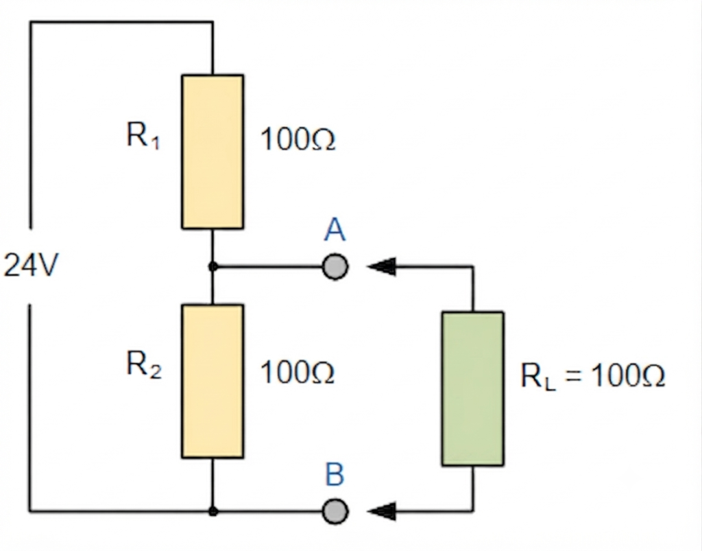
a) Without RL connected
a) RL connected
From the above calculations, the output voltage (Vout) is 12 V when the load resistor (RL) is not connected. However, after connecting the load, the output voltage decreases to 8 V. This reduction occurs because the load resistor forms a parallel combination with R₂, reducing the effective resistance of the lower branch and changing the voltage divider ratio.
This example demonstrates an important characteristic of a voltage divider circuit. The output voltage remains constant only when no external load is connected or when the load resistance is significantly larger than the divider resistors. As the load resistance decreases, more current is drawn from the circuit, causing a greater voltage drop and reducing the available output voltage. This phenomenon is known as the loading effect.
To minimize the loading effect, the load resistance should be much higher than the equivalent resistance of the voltage divider. Under these conditions, the current drawn by the load is very small, allowing the output voltage to remain close to its calculated value.
The reduction in output voltage caused by a voltage divider is commonly referred to as voltage attenuation. Therefore, when designing voltage divider circuits using resistors in series, the load impedance must always be considered to ensure accurate voltage levels. In applications where the output voltage needs to be adjusted, a potentiometer can be used instead of fixed resistors. Since a potentiometer acts as a variable voltage divider, it provides a convenient way to obtain the required output voltage while also compensating for resistor tolerances.
Because of their simplicity and reliability, voltage divider circuits are widely used in electronic systems for biasing transistors, generating reference voltages, sensor interfacing, analog signal conditioning, and measurement circuits. In addition, the Voltage Divider Rule is an essential tool for analyzing more complex electrical networks that contain both series and parallel resistive branches.
Power Dissipation in Series Resistors
Each resistor converts electrical energy into heat.
Power is calculated using
or
The total circuit power equals the sum of the individual resistor powers.
Connecting Resistors in Series
Connecting resistors in series is a simple process in which each resistor is connected end-to-end, creating a single continuous path for current flow. Since there is only one current path, the same current passes through every resistor in the series connection.
Follow these steps to connect series resistors:
- Connect the first resistor to one terminal of the voltage source.
- Connect the second resistor to the free end of the first resistor.
- Continue adding resistors one after another until all the required resistors are connected in series.
- Connect the free end of the last resistor to the other terminal of the power supply to complete the circuit.
- Switch on the power supply and verify that the circuit is complete. The same current will flow through every resistor, while the supply voltage will be divided across the individual resistors according to their resistance values.
Applications of Resistors in Series
Applications of Resistors in Series
A series connection is one of the most widely used resistor configurations in electrical and electronic circuits. Because the same current flows through every resistor while the supply voltage is divided among them, resistors in series are ideal for applications that require voltage division, current control, and signal conditioning.
Some of the most common applications of series resistors include:
1. Voltage Divider Circuits
One of the primary uses of resistors in series is to create a voltage divider circuit. By selecting appropriate resistor values, different output voltages can be obtained from a single DC supply. Voltage dividers are widely used in power supplies, reference voltage circuits, and analog electronics.
2. LED Current Limiting
A resistor connected in series with an LED limits the current flowing through the device and prevents excessive current that could damage the LED. The resistor value is selected using Ohm’s Law to maintain the desired operating current.
3. Battery Voltage Monitoring
Series resistors are commonly used to reduce high battery voltages to safe levels before they are measured by analog-to-digital converters (ADCs) in microcontrollers, battery management systems, and monitoring equipment.
4. Biasing Electronic Devices
Voltage divider networks made from resistors in series are frequently used to provide stable bias voltages for transistors, operational amplifiers, and other semiconductor devices, ensuring proper circuit operation.
5. Test and Measurement Circuits
Many electronic measuring instruments use series resistor networks for signal attenuation, voltage scaling, and range selection. This allows instruments to measure a wide range of voltages safely and accurately.
6. Educational and Laboratory Experiments
Because they clearly demonstrate Ohm’s Law, Kirchhoff’s Voltage Law, and the Voltage Divider Rule, resistors in series are widely used in electrical engineering laboratories and educational experiments.
7. Sensor Interface Circuits
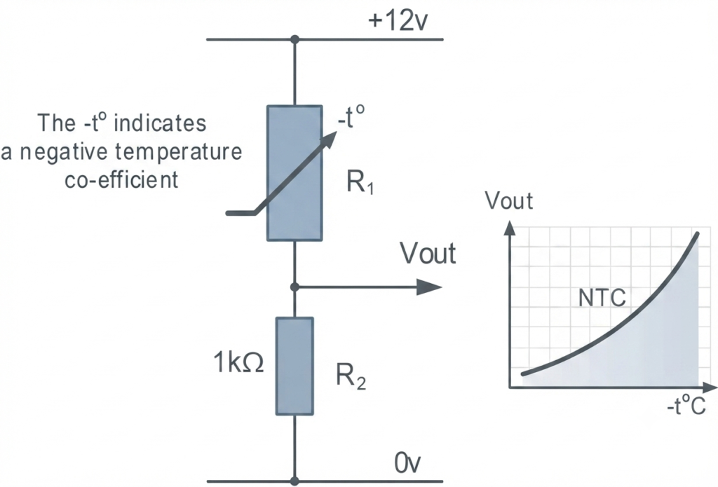
Many sensors, such as thermistors, light-dependent resistors (LDRs), and force-sensitive resistors (FSRs), are connected in series with a fixed resistor to form a voltage divider. As the sensor resistance changes, the voltage across the resistor in series also changes, allowing temperature, light intensity, pressure, or other physical quantities to be measured by a microcontroller or electronic circuit.
A practical application of resistors in series is a thermistor-based voltage divider. In the circuit shown below, a thermistor is connected in series with a fixed resistor. The thermistor has a resistance of 10 kΩ at 25°C and 100 Ω at 100°C. Using the Voltage Divider Rule, calculate the output voltage (Vout) at both temperatures.
1. At 25°C
At room temperature (25°C), the resistance of the thermistor (R1) is at its nominal value of 10 kΩ.
- R1 Resistance: 10,000 kΩ
- R2 Resistance: 10 kΩ
2. At 100°C
As the temperature increases to 100°C, the resistance of an NTC thermistor drops significantly.
- R1 Resistance: 100 Ω
- R2 Resistance: 10 kΩ
eplacing the fixed 1 kΩ resistor (R₂) with a potentiometer allows the output voltage to be adjusted as needed. This enables the voltage divider circuit to maintain the required output voltage over a broader temperature range and improves its adaptability to different operating conditions.
Advantages of Resistors in Series
Using resistors in series offers several benefits.
- Easy to design and calculate.
- Increases total resistance.
- Useful for voltage division.
- Requires simple wiring.
- Common in electronic circuits.
- Provides predictable current flow.
Disadvantages of Series Resistors
There are also some limitations.
- Failure of one resistor interrupts the entire circuit.
- Voltage is divided among resistors.
- Higher total resistance reduces current.
- Not suitable when independent operation is required.
Common Mistakes to Avoid
While working with resistors in series, beginners often make these mistakes:
- Adding voltages instead of resistances when finding equivalent resistance.
- Assuming current changes from one resistor to another.
- Ignoring unit consistency.
- Forgetting that the total voltage equals the sum of individual voltage drops.
- Using the parallel resistor formula for a series circuit.
Difference Between Series and Parallel Connection
Although series connection and parallel connection are the two basic ways of connecting resistors, they differ significantly in terms of current flow, voltage distribution, equivalent resistance, and circuit behavior. The table below highlights the key differences between resistors in series and resistors in parallel to help you understand when each type of connection should be used.
| Feature | Series Connection | Parallel Connection |
|---|---|---|
| Current | Same through all resistors | Divides between parallel branches |
| Voltage | Divided across the resistors | Same across every branch |
| Equivalent Resistance | Equal to the sum of all resistances | Always less than the smallest resistor |
| Current Path | One continuous path | Multiple current paths |
| Failure of One Resistor | Entire circuit stops operating | Remaining branches continue to operate |
Conclusion
Resistors in series are among the most commonly used components in electrical and electronic circuits because they provide a simple and reliable way to control current and divide voltage. In a series connection, the same current flows through every resistor, while the voltage across each resistor in series is proportional to its resistance. The total or equivalent resistance is obtained by adding the individual resistor values, making circuit analysis straightforward.
Understanding how series resistors behave is essential for applying Ohm’s Law, Kirchhoff’s Voltage Law, and the Voltage Divider Rule. These principles are widely used in practical applications such as voltage divider circuits, LED current limiting, sensor interfacing, transistor biasing, and measurement systems.
Whether you are working with two resistors in series, designing a voltage divider circuit, or calculating the voltage across resistors in series, mastering these concepts will help you analyze, design, and troubleshoot electrical and electronic circuits with confidence.
Read Next: