Learn about the center tapped full wave rectifier, its working, circuit diagram, characteristics, and applications. Explore how this rectifier efficiently converts AC to DC using a center-tapped transformer.
A center tapped full wave rectifier is a key component in electronics, responsible for converting alternating current (AC) to direct current (DC). By using a center-tapped transformer, this rectifier makes the conversion process more efficient by utilizing both halves of the AC signal.
In this article, we’ll break down the working of a center tapped full wave rectifier, review its circuit diagram, examine its characteristics, and discuss its applications in real-world electronics.
What is a Center Tapped Full Wave Rectifier?
A center tapped full wave rectifier is a type of rectifier that uses a transformer with a center tap. This transformer splits the AC voltage into two equal parts, allowing the rectifier to convert both halves of the AC waveform into pulsating DC.
Compared to half-wave rectifiers, which only convert one-half of the AC signal, a full-wave rectifier is much more efficient.
How Does a Center Tapped Full Wave Rectifier Work?

Here’s a simple explanation of how the center-tapped full-wave rectifier works:
1. Input AC Signal
The process starts with an input AC signal. This signal alternates between positive and negative cycles and is applied to the primary side of the center-tapped transformer.
2. Center-Tapped Transformer
The center-tapped transformer has a secondary winding with a central tap. This tap divides the secondary winding into two halves. Each half produces voltage during different halves of the AC cycle:
- During the positive half of the AC cycle, the upper half of the secondary winding generates positive voltage, while the lower half generates negative voltage.
- During the negative half of the AC cycle, the voltages are reversed.
3. Diode Operation
Two diodes (D1 and D2) handle the rectification process:
- In the positive half cycle, Diode D1 is forward-biased (it conducts), while Diode D2 is reverse-biased (it does not conduct).
- In the negative half cycle, Diode D2 is forward-biased (it conducts), while Diode D1 is reverse-biased.
This means that current flows in both halves of the AC cycle, allowing the rectifier to convert the entire AC signal into a pulsating DC output.
4. DC Output
The result is a pulsating DC output with a frequency double that of the input AC. So, if the input AC frequency is 50 Hz, the output DC will have a frequency of 100 Hz.
Circuit Diagram of a Center Tapped Full Wave Rectifier
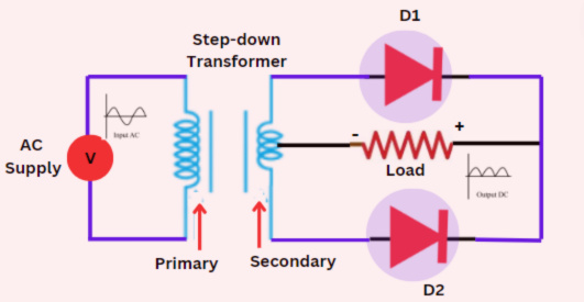
Below is a simple explanation of the circuit diagram for a center-tapped rectifier:
- Center-Tapped Transformer: Splits the AC voltage into two equal parts.
- Diodes (D1, D2): Rectify the AC signal into DC.
- Load Resistor (RL): Connected to the output, it converts the pulsating DC into usable power.
Here’s the Circuit Diagram of a Center Tapped Full Wave Rectifier:
Characteristics of a Center Tapped Full Wave Rectifier
The center-tapped rectifier has several important characteristics:
1. Efficiency
This rectifier is more efficient than a half-wave rectifier. Its efficiency is around 81.2%, meaning it converts most of the input power into useful DC output.
2. Output Frequency
The frequency of the output DC signal is twice the input AC frequency. For instance, if the AC input is 50 Hz, the output will be 100 Hz.
3. Ripple Factor
The ripple factor measures how smooth the output DC signal is. The ripple factor for a center-tapped full-wave rectifier is 0.48, which is lower than that of a half-wave rectifier. This means the output DC is smoother.
4. Peak Inverse Voltage (PIV)
Each diode in the rectifier needs to withstand a peak inverse voltage (PIV) equal to the peak value of the AC input voltage. It’s important to use diodes that can handle this voltage to avoid breakdown.
5. Transformer Utilization Factor (TUF)
The Transformer Utilization Factor (TUF) of this rectifier is 0.693. This indicates how effectively the transformer is being used during the rectification process.
Applications
The center-tapped rectifier has many uses in everyday electronics. Some of the most common applications include:
1. Power Supplies
These rectifiers are widely used in power supply circuits to convert AC into DC, which powers most electronic devices.
2. Battery Charging
In battery charging circuits, full wave rectifiers charge batteries efficiently by using both halves of the AC waveform.
3. Signal Demodulation
This rectifier is used in AM radio receivers for extracting the information signal from the modulated carrier wave.
4. Voltage Doublers
In certain circuits, center tap full wave rectifiers are used as voltage doublers, which can produce higher DC output voltage than the input AC voltage.
5. Welding Equipment
Some welding machines use full wave rectifiers to convert AC into DC, providing stable arc currents during welding.
Advantages of Center Tapped Full Wave Rectifier
- Higher Efficiency
- One of the main advantages is its high efficiency compared to a half-wave rectifier. Since it uses both halves of the AC waveform, it converts more of the input power into usable DC output.
- Efficiency is approximately 81.2%, making it ideal for applications that require stable and continuous DC power.
- Smoother DC Output
- The output frequency is double the input AC frequency, which results in a smoother DC output with fewer ripples.
- This smoother signal is critical for sensitive electronics and power supplies that require consistent DC.
- Better Transformer Utilization
- A center-tapped transformer improves transformer utilization, allowing the system to make better use of its capacity.
- The Transformer Utilization Factor (TUF) is around 0.693, which is better than the half-wave rectifier’s TUF.
- Full Use of the Input Signal
- This rectifier makes full use of both positive and negative halves of the input AC signal, doubling the output frequency and making the rectification process more effective.
- Lower Ripple Factor
- The ripple factor is much lower (approximately 0.48) compared to a half-wave rectifier. Lower ripple means the DC output is closer to a pure DC signal, reducing the need for additional filtering.
Disadvantages of Center Tapped Full Wave Rectifier
- Requires a Center-Tapped Transformer
- A significant drawback is the need for a center-tapped transformer, which can be more expensive and bulkier than a regular transformer.
- Additionally, center-tapped transformers are not always readily available, which adds to the complexity of the design.
- Diode Peak Inverse Voltage (PIV)
- Each diode must withstand a peak inverse voltage (PIV) equal to the full peak value of the AC input. This requires diodes with a higher voltage rating, which can increase the cost.
- If the diodes are not rated for the appropriate PIV, they could break down or fail, leading to circuit damage.
- Less Efficient Transformer Utilization
- Although the Transformer Utilization Factor (TUF) is better than that of a half-wave rectifier, it’s still not as high as bridge rectifiers, which don’t need a center-tapped transformer.
- In large-scale applications, bridge rectifiers can be more effective in terms of transformer utilization.
- More Complex Design
- The center-tapped full wave rectifier has a more complex design due to the need for additional components (like the center-tapped transformer and two diodes), making it harder to implement in simpler circuits.
- This complexity can lead to higher costs and larger circuit sizes.
Summary of Advantages and Disadvantages
| Advantages | Disadvantages |
|---|---|
| High efficiency (around 81.2%) | Requires center-tapped transformer |
| Smoother DC output with lower ripple | Higher peak inverse voltage (PIV) for diodes |
| Full use of both halves of the AC waveform | More complex design and higher cost |
| Better transformer utilization than half-wave | Less efficient transformer utilization than bridge rectifiers |
Conclusion
The center tapped full wave rectifier is a highly efficient and widely used method for converting AC to DC. Its ability to utilize both halves of the AC waveform makes it a better option than the half-wave rectifier, especially for applications like power supplies, battery charging, and signal demodulation.
Understanding its working principle, characteristics, and applications helps you appreciate its role in modern electronics. Whether you’re designing a power supply or working on a radio signal circuit, the center-tapped rectifier is a reliable choice for efficient AC to DC-conversion.
With its high efficiency and wide range of uses, the center tap full wave rectifier continues to be a critical component in electronics.