Boolean Algebra Truth Tables are used to represent how digital logic circuits behave for every possible combination of inputs. In simple terms, they visually map Boolean expressions to their corresponding logic gate outputs, helping engineers understand and design digital systems with accuracy.
Truth tables show how a logic gate—such as AND, OR, NOT, NAND, NOR, XOR, or XNOR—responds when inputs change from 0 (LOW) to 1 (HIGH). This makes Boolean Algebra Truth Tables a fundamental tool in digital electronics.
What Are Boolean Algebra Truth Tables?
A truth table is a tabular representation of all possible input combinations and their resulting outputs for a Boolean function or logic gate.
Instead of labeling inputs as ON/OFF, Boolean Algebra represents them as:
- 1 → TRUE / HIGH
- 0 → FALSE / LOW
Example: 2-Input Logic Circuit
For two inputs A and B, the possible combinations are:
- (0,0)
- (0,1)
- (1,0)
- (1,1)
Since each input has 2 possible states (0 or 1), the total combinations are:
- For 2 inputs → 2² = 4 combinations
- For 3 inputs → 2³ = 8 combinations
- For 4 inputs → 24 = 16 combinations
- For n inputs → 2ⁿ combinations
Boolean Algebra Truth Tables for Basic Logic Gates
Boolean Algebra Truth Tables For A 2-input AND Gate
For a 2-input AND gate, the output Q becomes true only when both input A and input B are true at the same time. This condition is represented by the Boolean expression: Q = A AND B.
The output is 1 only when both A AND B are 1.

Boolean Expression:
Q = A · B (read as “A AND B”)
Boolean Algebra Truth Tables For A 2-input OR Gate
For a 2-input OR (Inclusive-OR) gate, the output Q becomes HIGH whenever either input or input is HIGH. In simple terms, the Boolean expression for an OR gate is: Q=A+B, meaning the output is true if any one or both inputs are true.
The output is 1 if either A OR B is 1.

Boolean Expression:
Q = A + B
Boolean Algebra Truth Tables For The NOT Gate
For a single-input NOT gate (also called an inverter), the output becomes TRUE only when the input is FALSE. In other words, the NOT gate produces the inverse or complement of its input. The Boolean expression for a NOT gate is: Q = NOT A (read as “Q equals the inverse of A”).
The output is the opposite of the input.

Boolean Expression:
Q = NOT A or A̅
The NAND and NOR gates are special logic gates formed by combining the basic AND and OR gates with a NOT gate (inverter).
In simple terms, a NAND gate is an AND gate followed by inversion, while a NOR gate is an OR gate followed by inversion.
2-input NAND (Not AND) Gate
For a 2-input NAND gate, the output becomes FALSE only when both inputs and are TRUE. In every other case, the output remains TRUE. The Boolean expression for a NAND gate is:
Q = NOT (A AND B).
Outputs 0 only when both inputs are 1.

2-input NOR (Not OR) Gate
For a 2-input NOR gate, the output is TRUE only when both inputs and are FALSE. In simple terms, a NOR gate gives a HIGH output only if neither input is true. The Boolean expression for the NOR gate is:
Q = NOT (A OR B).
Outputs 1 only when both inputs are 0.

Besides the basic logic gates, there are two additional and widely used gate functions: the Exclusive-OR (XOR) gate and the Exclusive-NOR (XNOR) gate. Their Boolean operations are represented using a plus sign inside a circle, written as the symbol ⊕.
Although XOR and XNOR operations can be constructed by combining standard gates such as AND, OR, and NOT, they are used so frequently that they are now available as independent logic gate ICs. These gates are commonly included in digital circuit references due to their importance in arithmetic operations, parity checking, and control systems.
2-input EX-OR (Exclusive OR) Gate
For a 2-input XOR (Exclusive-OR) gate, the output Q becomes HIGH only when exactly one of the two inputs is HIGH. This means the gate produces a true output when A is 1 and B is 0, or A is 0 and B is 1, but not when both inputs have the same value.

Boolean Expression:
Q = A ⊕ B
2-input EX-NOR (Exclusive NOR) Gate
For a 2-input XNOR (Exclusive-NOR) gate, the output Q is HIGH only when both inputs are identical. This means the gate produces a true output when A and B are both 1 or when A and B are both 0. In simple terms, the XNOR gate checks for equality between the two inputs.

Summary of 2-Input Logic Gate Truth Tables
| A | B | AND | NAND | OR | NOR | XOR | XNOR |
| 0 | 0 | 0 | 1 | 0 | 1 | 0 | 1 |
| 0 | 1 | 0 | 1 | 1 | 0 | 1 | 0 |
| 1 | 0 | 0 | 1 | 1 | 0 | 1 | 0 |
| 1 | 1 | 1 | 0 | 1 | 0 | 0 | 1 |
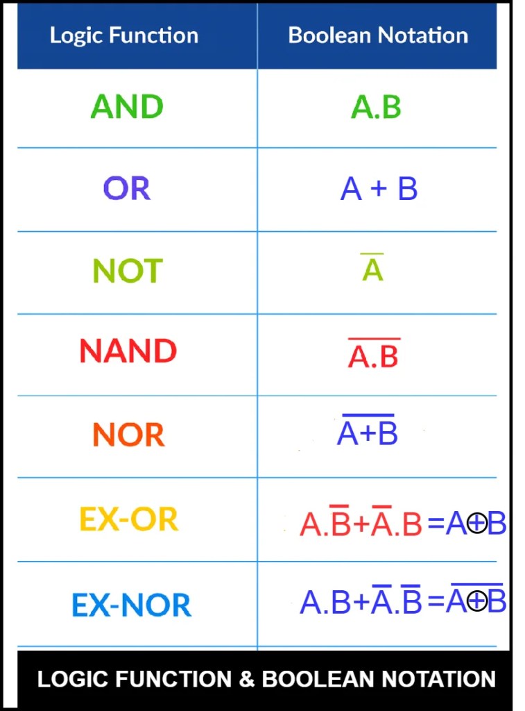
Common Boolean Notations
Why Boolean Algebra Truth Tables Matter
Boolean Algebra Truth Tables simplify circuit design, analysis, troubleshooting, and optimization. Whether working with microprocessors, embedded systems, or digital controllers, these tables provide a clear and structured way to understand signal behavior.
Conclusion
Understanding Boolean Algebra Truth Tables is essential for mastering digital electronics. They help you visualize how inputs affect outputs, simplify Boolean expressions, and design reliable logic circuits. Whether you’re learning basics or designing advanced digital systems, Boolean Algebra Truth Tables remain a foundational tool in electronics and computing.
Related Articles: