Electrical circuits often require components that control current and voltage. One of the most important circuit configurations used in electronics and electrical engineering is Resistors in Parallel.
When resistors are connected in this way, they provide multiple paths for current to flow, which changes how the overall resistance behaves in the circuit.
Understanding resistors in parallel is essential for students, engineers, and anyone studying circuit design. In this article, we will explore the concept of parallel connected resistors, explain the parallel resistance formula, derive the resistor in parallel formula, and solve example problems to help you clearly understand how resistance works in parallel circuits.
What Are Resistors in Parallel?
In electrical circuits, Resistors in Parallel occur when two or more resistors are connected across the same pair of nodes. This means that both terminals of each resistor are attached to the same two connection points in the circuit. In the following resistors in parallel circuit, the resistors R₁, R₂, and R₃ are all connected together between the two points A and B, forming multiple paths for current to flow.
Unlike a series circuit where current travels through a single path, a parallel resistor network allows electric current to move through several branches at the same time. Because the current divides among these different paths, parallel circuits are commonly referred to as current divider circuits.
When resistors are connected in parallel, the total current supplied by the source splits into different portions depending on the resistance of each branch. A branch with lower resistance will allow more current to pass through it, while a branch with higher resistance will carry less current. Although the current in each branch may vary, one important property remains constant—the voltage across every resistor is the same.
Since all the resistors are connected directly across the same two nodes, each resistor experiences the same potential difference as the supply voltage. For example, in a circuit where R₁, R₂, and R₃ are connected between nodes A and B, the voltage across R₁ is equal to the voltage across R₂, and the voltage across R₂ is equal to the voltage across R₃. In fact, each resistor has the same voltage as the power source connected to the circuit.
Key Characteristics of Resistors in Parallel
A circuit with parallel resistance has several important characteristics:
A circuit with parallel resistance has several important properties:
- Equal Voltage Across All Resistors
Each resistor experiences the same voltage because they are connected across the same two points. - Current Splits Across Branches
The total current divides among the different parallel paths. - Equivalent Resistance Decreases
Adding more resistors in parallel reduces the total resistance. - Independent Operation
If one branch stops working, the other branches can still function.
These properties make parallel circuits extremely useful in household wiring, electronics, and industrial power systems.
Understanding Resistance in Parallel
When studying resistance in parallel, it is important to remember that electric current does not travel through a single route. Instead, it distributes itself among all the available branches in the network.
The current flowing through each resistor depends on its resistance value. A lower resistance allows a larger amount of current to pass through that branch, while a higher resistance restricts the current flow.
This behavior follows Ohm’s Law, which explains the relationship between voltage, current, and resistance in electrical circuits:
V=IR
Where:
- V represents voltage
- I represents current
- R represents resistance
By applying Ohm’s Law, it becomes possible to calculate the current flowing through each resistor in a parallel network. Because of these characteristics, parallel resistor circuits are widely used in household wiring, electronic devices, and industrial power systems where maintaining the same voltage across multiple components is essential.
Parallel Resistor Circuit

In a Resistors in Parallel network, the way total resistance is calculated is different from a series circuit. In a series arrangement, the total resistance RT is simply the sum of all individual resistances connected one after another.
However, when resistors are connected in parallel, the calculation of the total or equivalent resistance follows a different approach. Instead of adding the resistance values directly, we add the reciprocal values of each resistor. The reciprocal means taking 1 divided by the resistance (1/R) for every resistor in the circuit.
After adding these reciprocal values together, the reciprocal of that total gives the equivalent resistance of the parallel network. This method is known as the parallel resistance formula, and it helps determine the overall resistance when multiple resistors share the same two connection points in a circuit.
Because current has several possible paths in a parallel circuit, the combined resistance is always lower than the smallest individual resistor in the network. This property makes parallel resistor circuits useful in many electrical and electronic applications where reduced resistance and multiple current paths are required.
Parallel Resistance Formula
To calculate the total resistance of multiple resistors connected in parallel, we use the parallel resistance formula.

Where:
- Req = Equivalent resistance
- R1,R2,R3 = Individual resistances
- n = Number of resistors
This resistors in parallel equation shows that the reciprocal of the equivalent resistance equals the sum of the reciprocals of individual resistances.
This formula is widely used in circuit analysis and electrical engineering calculations.
In a Resistors in Parallel network, the concept of Electrical Conductance is useful for understanding how easily current flows through the circuit. Conductance is represented by the symbol G, and its unit is the siemens (S). It is defined as the reciprocal (inverse) of resistance:
G=1/R1
This relationship shows that when resistance decreases, conductance increases, allowing more current to pass through the circuit. In parallel resistor networks, conductance values can be added together to simplify calculations. If the conductance of the circuit is known, the equivalent resistance RT can be found by taking the reciprocal of the total conductance.
Resistors are considered to be in parallel when they are connected between the same two nodes in a circuit. A parallel resistive circuit can appear in several different layouts, and resistors may be arranged in multiple configurations while still maintaining a parallel connection between the same two points.
Derivation of the Resistance Formula in Parallel
To derive the resistance formula in parallel, consider a circuit with voltage V connected across three resistors R1,R2, and R3.

Since the resistors are in parallel:
- Voltage across each resistor is the same.
- Current divides into three branches.
Let:
- I1 be current through R1
- I2 be current through R2
- I3 be current through R3
The total current entering the circuit is:
I=I1+I2+I3
Using Ohm’s law:

Substituting these values gives:

Dividing both sides by V:

Taking the reciprocal of both sides gives the parallel resistance formula:

The above equation becomes the parallel resistance formula.
Formula for Resistor in Parallel (Two Resistors)
When only two resistors are connected in parallel, a simpler formula can be used.
This shortcut formula is:

This formula for resistor in parallel is called the product-over-sum rule and is widely used in quick circuit calculations.
Special Case: Equal Resistors in Parallel
When several resistors with the same resistance value are connected in parallel, the equivalent resistance can be calculated easily.
The formula becomes:

Where:
- R = resistance of one resistor
- n = number of resistors
Example: If four resistors each have a resistance of 24 Ω, the equivalent resistance will be:
RT=24/4 = 6Ω
This property is often used in designing circuits where a specific resistance value is needed.
Current in Parallel Circuits
In a parallel circuit, the total current entering the network is equal to the sum of the currents through each branch.
This rule is based on Kirchhoff’s Current Law, which states that the total current entering a node equals the total current leaving it.
Mathematically:

Where:
- I = Total current
- I1, I2, I3 = Currents through individual resistors
Since voltage across each resistor is the same, currents differ depending on resistance values.
Parallel resistor networks are often described as current divider circuits because the incoming supply current splits into several branches. Each resistor provides a separate path for the current, so a parallel circuit with N resistors will have N individual current paths. Even though the current divides among these branches, the voltage across every resistor remains the same because all components are connected across the same two nodes of the power source.
Another useful property of resistors in parallel is that their positions in the circuit can be swapped without affecting the overall behavior of the network. Interchanging the resistors does not change the equivalent resistance or the total current flowing in the circuit, since the electrical connections between the nodes remain unchanged.
Example Circuit:

Using our formula for two resistors connected in parallel, the total circuit resistance RT is calculated as:

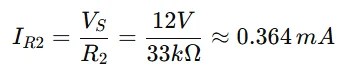
Using Ohm’s Law, the current flowing through each resistor in the parallel circuit can be determined. In this example, the supply voltage is 12 V, and the resistor values are R1=10kΩ and R2=33kΩ.
The current through resistor R1 is calculated as:

The current through resistor R2 is:
The total current IT in the parallel circuit is the sum of the branch currents:

This value can also be confirmed using Ohm’s Law with the equivalent resistance of the circuit (RT≈7.67kΩ):

Both calculations give nearly the same result, confirming that the total current in the parallel network is approximately 1.56 mA.
Various Parallel Resistor Circuits

Although the circuits shown above may appear different in structure, they are all configured as parallel resistor networks. Therefore, the same electrical principles and formulas used for resistors in parallel apply to each of these circuits.
Resistors in Parallel Example No1
Three resistors 7 Ω, 3 Ω, and 12 Ω are connected in parallel. Find the equivalent resistance.

Solution:
The total resistance RT across the two terminals A and B is:

This reciprocal method can be applied to determine the equivalent resistance for any number of resistors connected in a parallel circuit. It works by adding the reciprocals of each resistor’s value and then taking the reciprocal of that sum to obtain the total resistance.
However, when the circuit contains only two resistors in parallel, there is a faster and simpler approach. Instead of performing multiple reciprocal calculations, we can use a direct formula to find the equivalent resistance RT. This approach simplifies the process and reduces the amount of mathematical work involved.
The quicker product-over-sum formula for calculating the equivalent resistance of two parallel resistors—whether their values are the same or different—is given by:

Resistors in Parallel Example No2
Find the equivalent resistance of 33 kΩ and 150 kΩ connected in parallel.

Using the formula for two resistors connected in parallel, we can determine the total resistance of the circuit, denoted as RT, as follows:

An important concept to understand about resistors connected in parallel is that the total or equivalent resistance of the circuit (RT) is always smaller than the resistance of the smallest individual resistor in the network.
For instance, in the example discussed earlier, the equivalent resistance was calculated as RT = 27 kΩ, while the smallest resistor in the circuit has a value of 33 kΩ, which is clearly larger. This demonstrates that when resistors are connected in parallel, the resulting resistance of the circuit will always be lower than the smallest resistor present in the combination.
Another special case occurs when both resistors have the same value. If R1 = R2, the equivalent resistance of the parallel network becomes half of the value of one resistor, which can be written as R/2.
Similarly, when three or more resistors with identical resistance values are connected in parallel, the equivalent resistance can be determined using the formula:
RT = R / n
where R represents the resistance of one resistor and n represents the total number of resistors connected in parallel.
For example, if five resistors each having a resistance of 100 Ω are connected in parallel, the equivalent resistance of the circuit will be:
RT = R / n = 100 / 5 = 20 Ω
However, this simplified formula is valid only when all resistors have exactly the same resistance value. If the resistor values are different, the general parallel resistance formula must be used instead.
Resistors in Parallel Example No3
Determine the current flowing through each branch and the overall current supplied by the power source for the resistors arranged in the following parallel circuit.

Since the supply voltage is the same across every resistor in a parallel circuit, Ohm’s Law can be applied to determine the current flowing through each individual branch. Using this principle, the current in each resistor branch can be calculated based on its resistance value.
solution:

The total circuit current of 24.43 amperes can also be determined and confirmed by first calculating the equivalent resistance (RT) of the parallel network and then dividing the supply voltage (VS) by this resistance, as shown below.
Equivalent resistance calculation:

Then the current flowing in the circuit is:

Applications of Parallel Resistance
- Household Electrical Wiring
In most residential electrical systems, appliances and devices are connected in parallel. This ensures that each appliance receives the same supply voltage and can operate independently without affecting other devices in the circuit. - Electronic Circuits
Parallel resistors are commonly used in electronic circuits and integrated systems to control and distribute current. They help stabilize circuits, protect components, and maintain proper operation of electronic devices. - Power Distribution Systems
In power distribution networks, multiple electrical loads are connected in parallel so that each device can draw the required current from the same power source. This configuration allows different machines or equipment to operate simultaneously and independently. - Current Divider Circuits
Parallel resistor networks are used in current divider circuits to split current between different branches. These circuits are commonly found in measurement devices, sensors, and electronic instrumentation systems. - Improved System Reliability
Parallel circuits increase the reliability of electrical systems. If one resistor or branch fails, the remaining branches can continue operating, allowing the circuit to function without complete system failure.
Advantages of Resistors in Parallel
Parallel resistor circuits offer several benefits:
- Provide multiple current paths
- Reduce total resistance
- Maintain equal voltage across components
- Increase circuit reliability
- Allow independent device operation
Because of these advantages, parallel resistance networks are commonly used in modern electrical design.
Important Rules for Parallel Circuits
When working with resistors in parallel, remember these rules:
- Voltage across each resistor is the same.
- Current divides among branches.
- Equivalent resistance is less than the smallest resistor.
- Reciprocal addition is used for calculations.
- Adding more resistors decreases total resistance.
These rules make it easier to analyze parallel circuits quickly.
Summary
Resistors in parallel are connected across the same two nodes in a circuit, creating multiple current paths while maintaining equal voltage across each resistor.
The total resistance of such a network is calculated using the parallel resistance formula, which states that the reciprocal of the equivalent resistance equals the sum of the reciprocals of the individual resistances.
Key points to remember:
- Voltage across parallel resistors is constant.
- Current divides across branches.
- Equivalent resistance decreases when resistors are added.
- The resistor in parallel formula helps quickly calculate resistance for two resistors.
Understanding parallel connected resistors and the formula for resistors in parallel is essential for analyzing and designing electrical circuits.
Read Next: