Explore the types of transistors including BJT, JFET, MOSFET, and FET. Learn their working principles, applications, advantages, and key differences to choose the right transistor for your electronics project.
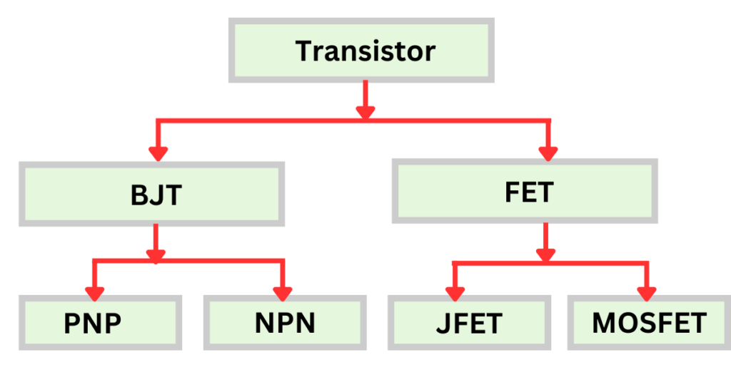
Transistors form the backbone of modern electronics, playing a crucial role in switching, amplification, and signal modulation. Transistors come in various forms, each offering distinct features that make them ideal for different applications. This article highlights four primary types: BJT (Bipolar Junction Transistor), JFET (Junction Field-Effect Transistor), MOSFET (Metal-Oxide-Semiconductor Field-Effect Transistor), and FET (Field Effect Transistor), explaining their unique characteristics and uses. Let’s explore how each of these works and where they are commonly used.
Types of Transistors
1. Bipolar Junction Transistor (BJT)
The BJT, being one of the earliest types of transistors, has found extensive use in amplification circuits due to its reliable performance. It operates by using two types of charge carriers, electrons, and holes, hence the term “bipolar.” A BJT consists of three semiconductor layers that create two junctions: emitter, base, and collector.
The image below illustrates the appearance of a typical BJT in a practical setting.
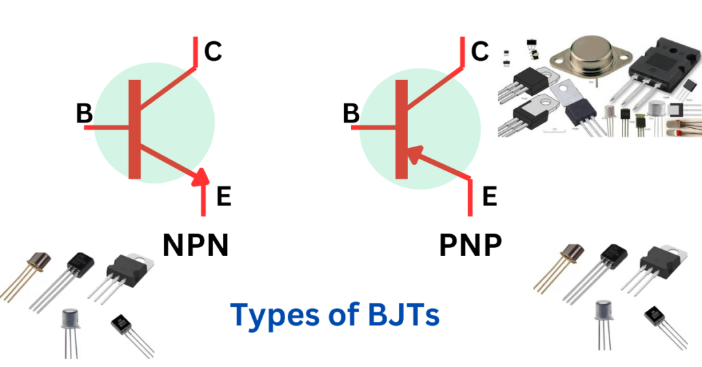
- NPN Transistor: In this setup, a small current applied to the base enables a much larger current to pass from the collector to the emitter
- PNP Transistor: In this case, the current moves from the emitter to the collector when a small negative voltage is introduced to the base.
BJT Terminals:
A Bipolar Junction Transistor (BJT) has three terminals, which are essential for its operation in amplifying or switching applications. The terminals are:
- Emitter (E):
- The emitter is heavily doped and responsible for supplying charge carriers (electrons or holes) to the base region.
- In an NPN transistor, the emitter emits electrons, while in a PNP transistor, it emits holes.
- Base (B):
- The base is thin and lightly doped. It regulates the flow of charge carriers between the emitter and collector, determining how much current passes through the transistor.
- It plays a crucial role in the transistor’s amplification properties.
- Collector (C):
- The collector is moderately doped and larger compared to the emitter. It collects the charge carriers emitted from the emitter through the base.
- This terminal is responsible for gathering the majority of the charge carriers that move through the transistor.
These terminals work together to control the current flow and determine the operation of the BJT, whether it functions as an amplifier or a switch.
Working of a BJT:
BJTs amplify electrical signals by using a small current at the base to regulate a larger current flowing between the collector and emitter. This makes them perfect for signal amplification and switching.
Applications of BJTs:
- Audio and radio signal amplification
- Switching in circuits like relays
- Motor control circuits
Advantages:
- High current gain and good amplification capabilities
- Easy to use for switching applications
Disadvantages:
- Consumes more power compared to other transistors
- Heat management is required for higher currents
2. Field Effect Transistor (FET)
The FET is a type of transistor that regulates current flow by applying a voltage to its gate terminal. Unlike BJTs, FETs use only one type of charge carrier, either electrons or holes, making them unipolar devices.
The two major types of FETs are JFET and MOSFET.
FET Terminals:
A Field Effect Transistor (FET) has three key terminals that manage its operation in circuits, such as amplifiers or switches:
- Source (S):
- This is the terminal where carriers (electrons for N-channel or holes for P-channel) enter the transistor, starting the flow of current through the device.
- Gate (G):
- The gate regulates the flow of carriers between the source and the drain by applying an electric field. The voltage applied here determines whether the FET is conducting or not.
- Drain (D):
- The drain is the terminal where the carriers leave the transistor after traveling through the channel from the source, completing the current flow.
Together, these terminals control how the FET operates, with the gate managing whether current flows between the source and drain.
How FET Works:
Current passes through the channel between the source and drain, with this flow being regulated by the voltage applied to the gate. A standout feature of FETs is their high input impedance, enabling efficient performance with very little input current.
Applications of FETs:
- Amplification in low-noise, high-frequency circuits
- Analog switches
- Impedance buffering
Advantages:
- Lower power consumption due to high input impedance
- Reduced noise, making it suitable for sensitive applications
Disadvantages:
- Can’t handle as much current as BJTs
- More vulnerable to damage from static electricity
3. Junction Field-Effect Transistor (JFET)
The JFET, a specific type of Field Effect Transistor (FET), manages current flow using an electric field. Unlike BJTs, JFETs are unipolar, meaning they depend solely on one type of charge carrier—either electrons in N-type or holes in P-type materials. JFETs are composed of three terminals: the source, gate, and drain.
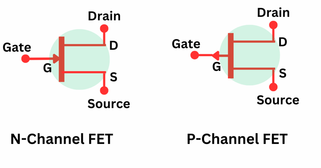
The symbols of a JFET for N-channel and P-channel FETs are depicted below.
How JFET Works:
In a JFET, current moves from the source to the drain, with the gate voltage regulating this flow by generating an electric field. Unlike BJTs, no current flows into the gate, making JFETs more power-efficient.
Applications of JFETs:
- Voltage amplifiers
- Buffer circuits in analog electronics
- Low-noise amplifiers
Advantages:
- Minimal power usage as a result of its high input impedance.
- Suitable for high-frequency applications
Disadvantages:
- Limited current handling compared to BJTs
- Less efficient at switching large currents
4. Metal-Oxide-Semiconductor Field-Effect Transistor (MOSFET)
MOSFETs are the most commonly used transistors in modern digital circuits. They function by regulating the voltage at the gate, which is separated from the conducting channel by a thin oxide layer. MOSFETs are available in two primary types: N-channel and P-channel.
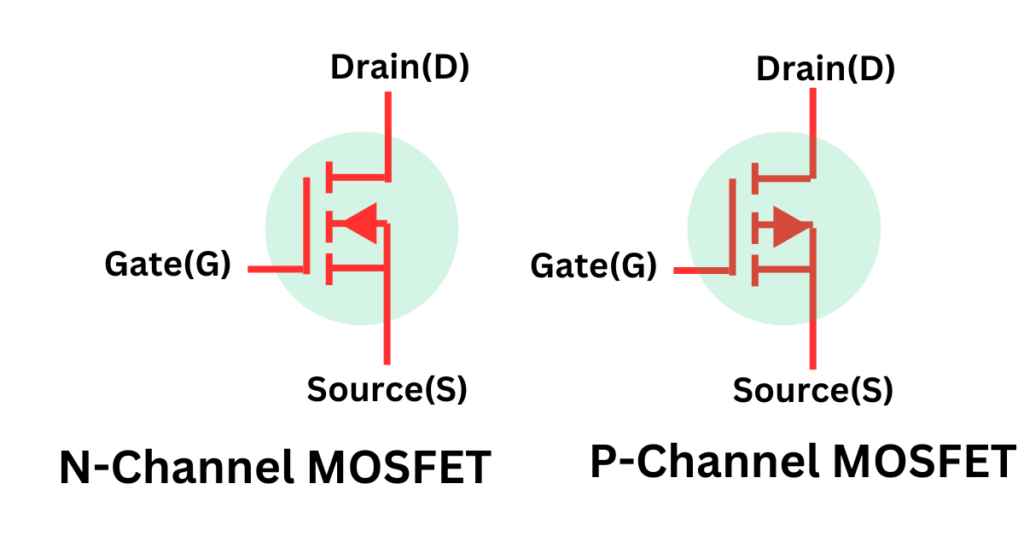
- N-channel MOSFET: Relies on electrons as the main charge carriers, offering high efficiency and rapid switching capabilities.
- P-channel MOSFET: Employs holes as the main charge carriers, allowing current to flow from the source to the drain.
The symbol of N-channel and P-channel MOSFET is,
How MOSFET Works:
MOSFETs function by applying voltage to the gate, creating an electric field that regulates the current through a channel between the source and drain. The gate’s insulation enables efficient switching between on and off states, resulting in low power consumption and high efficiency.
Applications of MOSFETs:
- Microprocessors and memory chips
- Power regulators and converters
- Digital logic gates
Advantages:
- High-speed switching and energy efficiency
- Ideal for low-power, high-performance applications
Disadvantages:
- Sensitive to static discharge, requiring careful handling
- More complex to fabricate compared to other transistors
Advantages:
- Lower power consumption due to high input impedance
- Reduced noise, making it suitable for sensitive applications
Disadvantages:
- Can’t handle as much current as BJTs
- More vulnerable to damage from static electricity
Conclusion
Understanding the types of transistors is essential for selecting the right one for your project. BJTs are ideal for amplification and handling high current, whereas JFETs and FETs are better suited for low-power, high-frequency applications. MOSFETs, meanwhile, dominate in digital circuits due to their efficiency and fast switching abilities. Each type has its own strengths and weaknesses, making them suitable for different use cases. The right choice depends on your specific electronic application.