In electronics, one of the simplest yet most important components is the pull up resistor. Although it’s just a resistor tied to the supply rail, this biasing element prevents many unpredictable problems in circuits. If you’ve ever wondered what it does, how it works, how to calculate the correct value, or how it differs from a pull-down resistor, this guide explains everything step by step.
What is a Pull Up Resistor?
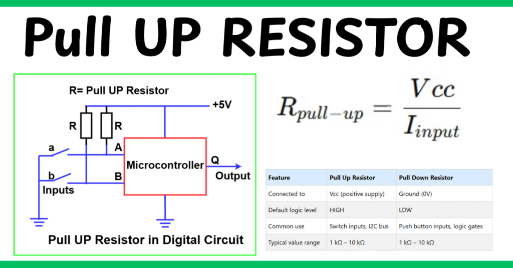
A pull up resistor is a resistor that connects an input pin to the positive voltage supply (Vcc). Its main role is to ensure the input has a default logic HIGH when no other active component is driving it.
- Without a Vcc connected resistor, the input pin would be left floating, meaning it could randomly read HIGH or LOW.
- Floating inputs cause noise, unstable operation, and false triggers in digital circuits.
For example, in a microcontroller-based project, if you connect a push button without a resistor, the input pin will fluctuate when the button is not pressed. Adding a pull up resistor stabilizes the pin.
Why Do We Need a Pull Up Resistor?
The function of a pull up resistor is critical in digital electronics:
- Prevents undefined states: Ensures a pin always reads a valid HIGH or LOW.
- Stabilizes signals: Avoids false switching caused by floating inputs.
- Provides default logic: Keeps the circuit in a known state when switches or sensors are idle.
- Used in communication buses: Protocols like I2C depend on pull up resistors to ensure proper data transfer.
Without a resistor connected to VCC, circuits become unpredictable and unreliable.
Pull Up Resistor in Digital Circuit
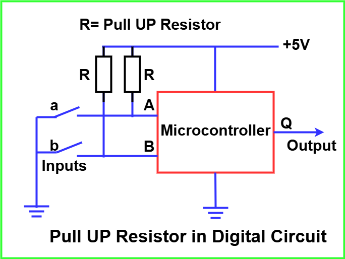
Let’s consider a switch connected to a microcontroller input pin. The role of the pull-up resistor here is to ensure that the pin always has a defined logic level:
- When the switch is open:
- The pull-up resistor connects the input pin to Vcc.
- The microcontroller reads the pin as HIGH (logic 1).
- When the switch is closed:
- The input pin is directly connected to ground (GND).
- The microcontroller reads the pin as LOW (logic 0).
Without the pull-up resistor, the input pin would “float” when the switch is open, leading to unstable or noisy readings.
Many microcontrollers (e.g., Arduino, ESP32, PIC) have built-in pull-up resistors that can be enabled via software, which eliminates the need for external resistors in simple circuits.
Pull Up Resistor Value
Choosing the right resistor value is crucial.
- If the value is too high (e.g., 100 kΩ), the pin may not pull up fast enough → signal becomes weak and prone to noise.
- If the value is too low (e.g., 100 Ω), the circuit will waste power because too much current flows when the input is pulled LOW.
Common range:
- 1 kΩ to 10 kΩ → General purpose digital circuits.
- 4.7 kΩ to 10 kΩ → I2C communication bus.
- 100 kΩ or higher → Low-power battery circuits where speed is less important.
Pull Up Resistor Calculation
The correct resistor value depends on:
- Supply Voltage (Vcc): Usually 3.3V or 5V.
- Input current of the pin: Typically in the microamp range for CMOS logic.
- Speed requirement: Faster switching → lower resistor value.
Formula for Approximate Value:
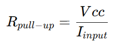
Where:
- Vcc = Supply voltage
- Iinput = Current needed when pin is LOW
Example:
For a 5V microcontroller pin requiring ~1 mA when LOW:
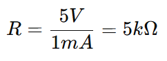
A 4.7 kΩ pull up resistor would be a practical choice.
Pull Down Resistor vs Pull Up Resistor: Key Differences
A pull down resistor works opposite to a pull up resistor. Instead of connecting to Vcc, it connects the pin to ground (0V). This ensures the pin stays LOW when idle.
| Feature | Pull Up Resistor | Pull Down Resistor |
| Connected to | Vcc (positive supply) | Ground (0V) |
| Default logic level | HIGH | LOW |
| Common use | Switch inputs, I2C bus | Push button inputs, logic gates |
| Typical value range | 1 kΩ – 10 kΩ | 1 kΩ – 10 kΩ |
Rule of thumb: Use a pull up when you want the default state to be HIGH, and a pull down when you want the default state to be LOW.
Applications of Pull Up Resistors
Pull up resistors are used in many circuits, including:
- Microcontrollers (Arduino, Raspberry Pi, ESP32): For stable GPIO inputs.
- Communication protocols: I2C and 1-Wire need pull ups on data lines.
- Switch circuits: Ensures reliable button press detection.
- Reset pins of ICs: Keeps devices in a default state until triggered.
- Open-collector outputs (like transistors): Require pull ups to function properly.
Common Mistakes When Using Biasing Resistors
While these resistors are simple to use, beginners often make a few mistakes:
- Using very low resistance values – This causes unnecessary current flow, leading to wasted power and heating issues.
- Choosing extremely high resistance values – In this case, the pin might not rise quickly to a stable logic level, making the signal prone to noise.
- Ignoring built-in options – Many microcontrollers already provide internal biasing resistors that can be activated by software. Overlooking this feature adds unnecessary external components.
- Not matching speed requirements – Fast digital buses like I²C or SPI often require carefully selected resistance values to ensure reliable communication.
By avoiding these mistakes, you can design circuits that are more efficient, stable, and reliable.
Conclusion
A pull up resistor is one of the simplest yet most essential components in electronics. It ensures input pins don’t float and instead remain at a defined voltage. By selecting the right value (typically between 1 kΩ and 10 kΩ), you can build circuits that stay stable, reliable, and free from noise issues.
Whether you are building a switch input circuit, using a microcontroller GPIO, or working with I2C communication, understanding resistor for input stabilization function and calculation is key to avoiding errors.
FAQs on Pull Up Resistors
The input will float, causing random HIGH/LOW readings and unstable circuit behavior.
No, they work in opposite directions. Using both simultaneously can create a constant current path (short between Vcc and GND).
Usually 10 kΩ for push buttons. Internal pull ups (~20–50 kΩ) can also be enabled in code.
Because I2C devices have open-drain outputs and cannot drive the line HIGH by themselves. Pull ups ensure proper logic HIGH levels.
Related Articles: