A summing amplifier is an op-amp circuit based on the inverting amplifier configuration. It combines two or more input signals into a single output voltage, where each input contributes according to its resistor value. The resulting output is the weighted sum of all the input voltages.
Summing Amplifier Op-amp Circuit
In a basic inverting or non-inverting op-amp circuit, a single input signal is amplified to produce one output signal. However, an op-amp can also be configured to accept several input signals at the same time. This configuration is known as a summing amplifier.
A summing amplifier, also called a summing inverter or voltage adder, is an op-amp circuit that combines multiple input voltages and produces a single output voltage. The contribution of each input depends on the resistance connected to that input, allowing the circuit to produce a weighted sum of the applied signals.
In a typical summing amplifier, each input voltage, such as , , and , is applied to the inverting terminal of the op-amp through a separate input resistor, such as , , and . The non-inverting terminal is connected to ground, while a feedback resistor connects the output to the inverting input.
The values of the input resistors and feedback resistor determine how strongly each input signal influences the final output voltage.
Summing Amplifier Circuit
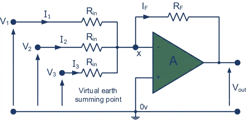
In a summing amplifier, the output voltage depends on the combined effect of the input voltages , , , and so on. By applying Kirchhoff’s Current Law (KCL) along with Ohm’s law, the standard inverting amplifier equation can be extended to include multiple input signals. The resulting expression gives the negative weighted sum of the applied input voltages, with each input contributing according to its corresponding resistance value.
Summing Amplifier Formula Derivation
Consider the summing amplifier shown in Figure-1. The circuit has three input voltages , , and , each connected to the inverting input of the op-amp through an input resistor. The feedback resistor connects the output back to the inverting terminal, while the non-inverting terminal is grounded.
For an ideal op-amp with negative feedback, the inverting terminal is at approximately 0 V. This point is called a virtual ground. Also, the op-amp input current is assumed to be zero. Therefore, the currents supplied by the input sources flow toward the summing point and through the feedback resistor.
Applying KCL at the Summing Point
Let the currents through the three input resistors be , , and . Using Ohm’s law:
Since the op-amp input draws no current, the total current flowing into the summing point must pass through the feedback resistor .
Therefore, applying Kirchhoff’s Current Law (KCL) at point :
Substituting the individual currents gives:
The voltage across the feedback resistor is related to the output voltage. Since the summing point is at virtual ground, its voltage is approximately V. Hence:
or
Equating the two expressions for :
Rearranging for the output voltage:
This is the general summing amplifier output equation. It shows that each input voltage is multiplied by a factor determined by the ratio of the feedback resistor to its corresponding input resistor.
When All Input Resistors Are Equal
If all input resistors have the same resistance,
the equation can be simplified by taking as a common factor:
If the feedback resistor is also equal to the input resistors, , the circuit becomes a unity-gain summing amplifier, giving:
The negative sign indicates that the output is inverted relative to the combined input signal.
Summing Amplifier Equation
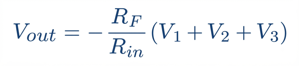
A summing amplifier can combine several input voltages and produce a single output voltage proportional to their algebraic sum. In the circuit shown, the input voltages , , and contribute to the output according to their respective resistor values.
Additional input signals can be connected by adding more input resistors. Each input is effectively independent because the virtual ground at the op-amp’s inverting terminal prevents the input signals from directly affecting one another.
When all input resistors have the same value and , the circuit provides a direct addition of the input voltages. Because the summing point is connected to the inverting input, the output represents the negative sum of the applied signals.
If the summing configuration is instead arranged at the non-inverting input, the resulting output can represent the positive sum of the input voltages, depending on the specific circuit configuration.
Scaling Summing Amplifier
A scaling summing amplifier uses the same basic inverting summing-amplifier configuration, but the input resistors are given different resistance values. This allows each input voltage to have a different effect, or weight, on the output voltage.
For the standard summing amplifier, when all input resistors are equal, each input contributes equally to the output. However, by selecting different values of , , , and so on, we can increase or decrease the contribution of individual input signals.
For example, if is smaller than , the current produced by will be greater than the current produced by , assuming the input voltages are equal. Therefore, will have a greater influence on the output.
Scaling Summing Amplifier Formula
Because each input has a different resistance, the output voltage is calculated by considering the contribution of each input separately:
This equation shows that the scaling factor for each input is determined by the ratio between the feedback resistor and its corresponding input resistor.
The individual contributions can therefore be written as:
Thus, the voltage gain for each input is:
This means that changing an individual input resistor changes the gain applied to that particular input without directly changing the scaling of the other inputs.
Choosing the Feedback Resistor
The equation can also be rearranged to determine the required feedback resistance for a desired output voltage.
Rearranging to make the subject gives:
This form is useful when designing a scaling summing amplifier because the required feedback resistor value can be calculated once the input voltages, input resistor values, and desired output voltage are known.
The negative sign is a consequence of using the inverting input of the op-amp. Therefore, the output voltage has the opposite polarity to the weighted sum of the input voltages.
Unity Gain Summing Amplifier
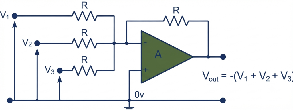
A unity gain summing amplifier is a summing circuit in which all the input resistors have the same resistance, and the feedback resistor is also selected to have the same value. This arrangement gives each input signal a gain of .
For example, if:
the general summing amplifier equation becomes:
Thus, the circuit adds all the input voltages together while reversing their polarity. Each input contributes equally to the final output because all input resistors have identical values.
The summing amplifier is a flexible op-amp circuit that can combine several independent signals into a single output. By simply changing the input resistor values, its operation can be changed from equal-gain addition to weighted addition.
When , , , and other input resistors are equal, the circuit functions as a unity-gain inverting adder. When these resistors have different values, each input receives a different gain, creating a scaling summing amplifier that produces a weighted sum of the input signals.
Summing Amplifier Worked Example No. 1
Find the output voltage of the following summing amplifier circuit.
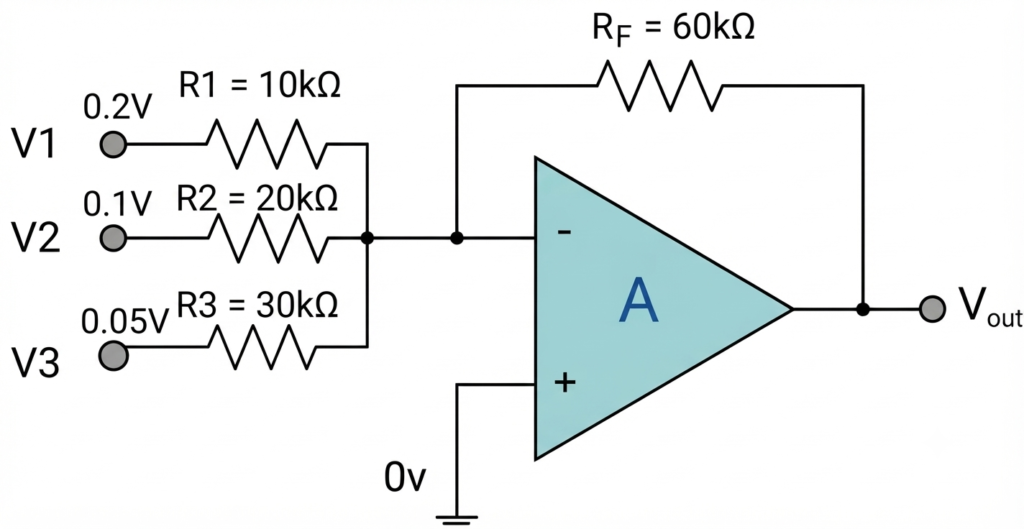
In this example, the circuit has three input signals with different input-resistor values. The values are:
The circuit is a scaling summing amplifier because the input resistors have different values.
Solution
For an inverting summing amplifier, the output voltage is:
Substituting the given values:
Calculating each term:
Therefore:
Non-Inverting Summing Amplifier
In addition to the inverting configuration, an op-amp can also be arranged as a non-inverting summing amplifier, where multiple input signals are combined at the non-inverting terminal.
As discussed earlier, an inverting summing amplifier generates the negative sum of its applied input voltages. Therefore, a properly designed non-inverting summing amplifier produces an output corresponding to the positive sum of its input signals.
The non-inverting summing amplifier follows the basic arrangement of a non-inverting operational amplifier. The input signals, whether AC or DC, are applied to the non-inverting (+) terminal. Meanwhile, the inverting (-) terminal receives negative feedback from the output through a resistor network. This feedback network determines the required voltage gain and maintains stable amplifier operation.
Non-inverting Summing Amplifier Circuit
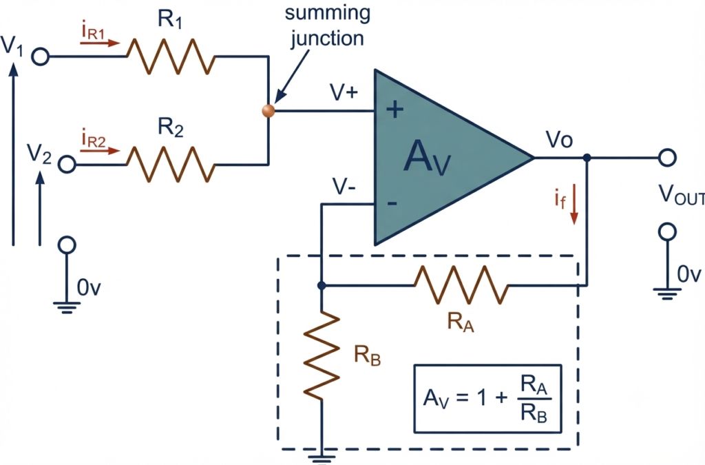
The non-inverting summing amplifier provides a way to combine multiple input signals while maintaining the same polarity at the output. Unlike the inverting summing amplifier, the output voltage is in phase with the combined input signal. The contribution of each input can be controlled through the associated resistor values, allowing the circuit to perform weighted addition.
Another useful feature is that the input-summing network is not directly affected when the closed-loop gain of the op-amp is changed. However, designing the resistor network for different weighting factors can require additional calculations, particularly when several inputs have different resistor values. Using equal input resistances simplifies the analysis considerably.
If the closed-loop gain of the non-inverting amplifier is selected to equal the number of input signals, the output can become equal to the arithmetic sum of those inputs. Therefore, a two-input circuit requires a gain of 2, a three-input circuit requires a gain of 3, and so forth.
This operation results from the relationship between the currents through the input resistors and the voltages applied to the inputs. When the input resistors are equal, such as , the resistor network develops a voltage at the non-inverting input that represents the required combination of the input signals.
Derivation of the Output Voltage
For a two-input non-inverting summing amplifier, the input currents can be analyzed from the corresponding resistor network.
If the two input resistors are selected to have equal values:
Then.
The standard closed-loop voltage gain of the non-inverting amplifier is:
The closed-loop voltage gain of the non-inverting amplifier is given by . When , the gain becomes 2, making the output voltage equal to the sum of the input voltages.
Non-Inverting Output Voltage
If,
For a three-input non-inverting summing amplifier, setting the closed-loop voltage gain to 3 makes the output equal to the sum of the three input voltages:
Similarly, a four-input summing amplifier requires a closed-loop gain of 4, while a five-input version requires a gain of 5. In general, for equal inputs, the required closed-loop gain is .
There is also a useful averaging configuration. If the op-amp is connected as a unity-gain voltage follower, with and , the circuit has no additional voltage gain. In this arrangement, the output represents the average of the two input voltages:
Thus, by selecting appropriate input resistors and feedback components, the non-inverting summing amplifier can be configured for signal addition or signal averaging while preserving the input signal polarity.
Summing Amplifier Applications
Summing amplifiers are useful in many practical electronic circuits because they can combine multiple input signals into a single output. Both inverting and non-inverting configurations can be adapted for different applications by selecting suitable resistor values.
When the input resistors are connected to potentiometers, the contribution of each input signal can be adjusted independently. This allows several signals to be mixed in controlled proportions before producing the final output.
For example, in a temperature measurement circuit, a summing amplifier can add a suitable negative offset voltage to the sensor signal. This can shift the output so that the measured voltage or display reads 0 at the freezing point.
Another common application is an audio mixer. Signals from different sources, such as vocals, instruments, or microphones, can be applied to separate inputs. The summing amplifier combines these signals into one output waveform, which can then be fed to an audio amplifier or subsequent processing stage.
Thus, summing amplifiers are commonly used for signal mixing, voltage scaling, offset adjustment, audio processing, and analog signal conditioning.
Simple Audio Mixer Circuit
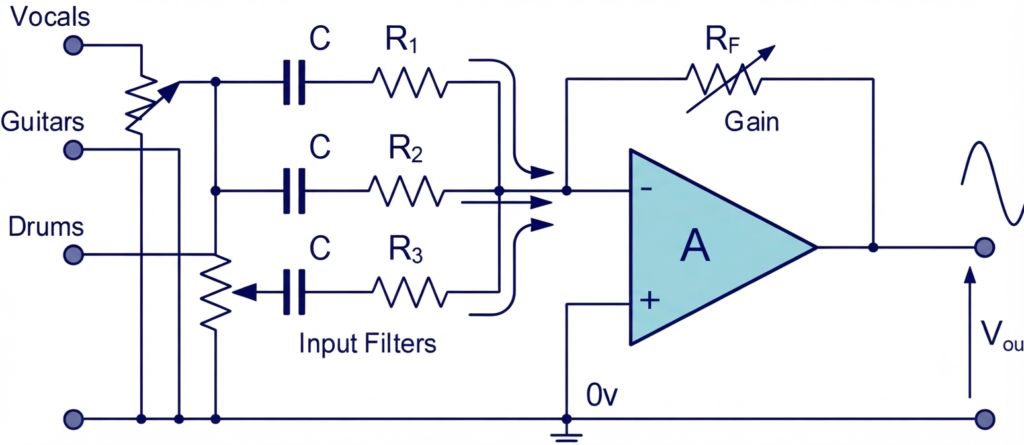
A summing amplifier can also be used to build a simple audio mixer. In this arrangement, audio signals from different sources are connected to separate inputs of the op-amp through individual resistors. The amplifier combines these signals into a single output signal, making it useful for mixing vocals, instruments, microphones, or other audio sources.
Another important application of the summing amplifier is a weighted-sum digital-to-analogue converter (DAC). In this configuration, the input resistors are selected with progressively increasing values so that each digital input contributes a different amount to the output.
For example, the input resistors can be chosen as:
Each resistor is twice the value of the preceding one. Digital input signals represented by logic 0 or logic 1 are then applied to these inputs. Because the input current is determined by the resistor value, each digital bit produces a different contribution to the output voltage.
The summing amplifier therefore combines these weighted contributions to generate an analogue voltage corresponding to the applied digital input. This principle forms the basis of a binary-weighted resistor DAC.
Digital-to-Analogue Converter (DAC)
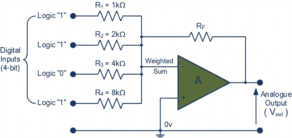
A summing amplifier can be used as a simple digital-to-analogue converter (DAC) by assigning different resistor values to the digital input bits. The circuit shown uses a 4-bit input, where each bit contributes a different amount to the final analogue output.
The number of bits in the digital input word determines the number of available output levels. For a 4-bit DAC, there are:
possible digital combinations. Therefore, the analogue output can change through 16 discrete levels between zero and the maximum output value.
The size of each output step depends on the full-scale output voltage and the number of available digital levels. For an ideal -bit DAC, the number of quantization levels is:
The accuracy of the resulting analogue voltage depends on several factors. The digital input levels must remain close to their intended logic values, such as 0 V for logic 0 and 5 V for logic 1 in a 5-V logic system. The accuracy and matching of the input resistors are also important because their values determine the weighting assigned to each digital bit.
In practical systems, achieving precise resistor ratios and stable logic levels can be challenging. For this reason, commercially available digital-to-analogue converters (DACs) are commonly used. Many DACs incorporate accurately matched resistor networks, including the widely used R-2R resistive network, to provide reliable and precise digital-to-analogue conversion.
Conclusion
A summing amplifier is an op-amp circuit designed to combine two or more input signals, whether AC or DC, into a single output. Depending on its configuration and resistor values, it can produce either an inverted or non-inverted sum of the applied inputs.
In an inverting summing amplifier, each input resistor controls the contribution of its corresponding input signal to the output. The non-inverting terminal is connected to ground, while negative feedback through keeps the inverting terminal close to 0 V, creating a virtual ground.
By selecting different input resistor values, the circuit can provide either equal or weighted contributions from the input signals. This makes the summing amplifier useful for applications such as audio mixing, signal conditioning, voltage addition, and digital-to-analogue conversion.
In the next operational amplifier tutorial, we will look at a circuit in which signals are applied to both the inverting and non-inverting inputs simultaneously. This configuration is known as a differential amplifier. Unlike a summing amplifier, a differential amplifier produces an output related to the difference between its input voltages.
Read Next:
- Inverting vs Non-Inverting Amplifier: Differences, Gain, and Applications
- Inverting Operational Amplifier: Circuit, Working, and Gain Formula
- Op-Amp Building Blocks: Basic Circuits and Applications
- Operational Amplifier (Op-Amp): Basics, Types, Working & Applications
- Non-inverting Operational Amplifier: Circuit, Gain & Formula