Op-Amp Building Blocks are fundamental components of analog electronic circuits. These op-amp building blocks can be configured in different ways to create a wide range of amplifier, filter, signal-processing, and other analog circuits.
Op-Amp Building Blocks for Analog Amplifier Design
Operational amplifiers, commonly known as op-amps, are essential building blocks in analog electronic circuit design. To simplify the topic, this guide presents several basic Op-Amp Building Blocks that can be used to develop different analog amplifier and filter circuits.
An operational amplifier is essentially a voltage-amplifying device designed to work with external feedback components, such as resistors (R) and capacitors (C), connected between its input and output terminals. By selecting these components appropriately, different amplifier configurations can be created, each providing a specific function and frequency response.
A typical operational amplifier is a five-terminal device with two input terminals, one output terminal, and two power-supply terminals. The inputs are known as the inverting input, marked −IN, and the non-inverting input, marked +IN.
An ideal op-amp is assumed to have infinite voltage gain for differential input signals. In practical devices, however, the low-frequency or DC open-loop voltage gain may be around 120,000, or approximately +100 dB, depending on the device.
An op-amp ideally provides zero gain for signals that are common to both input terminals. It also has very high input impedance and very low output impedance, making it suitable for a wide range of analog applications.
By using suitable external feedback components to control the closed-loop gain, different Operational amplifier Building Blocks can be developed, each with its own circuit function, gain, and frequency-response characteristics.
Voltage Follower: Unity-Gain Amplifier
A voltage follower, also known as a unity-gain buffer, does not amplify or invert the input signal. Instead, it reproduces the input voltage at the output while providing electrical isolation between the source and load circuits.
Because an operational amplifier has very high input impedance and low output impedance, a voltage follower draws very little current from the source and helps minimize loading effects. This makes it useful for impedance matching, signal buffering, and circuit isolation.
In this configuration, the output is directly connected to the inverting input, providing 100% negative feedback. The closed-loop voltage gain is approximately +1 (unity), so the output voltage follows the input voltage:
The Voltage Follower Op-amp Circuit

The Op-Amp Inverting Amplifier
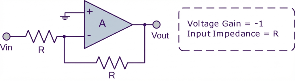
An inverting amplifier, sometimes referred to as an inverting buffer when configured for unity gain, produces an output that is opposite in phase to the input signal. When the input and feedback resistors have equal values, the circuit provides a voltage gain of −1, meaning the output voltage has the same magnitude as the input but with a 180° phase reversal.
The input impedance of the circuit is determined primarily by the input resistor . For equal input and feedback resistances, the output is therefore:
This configuration is useful when a signal needs to be inverted while maintaining approximately the same voltage magnitude.
The Basic Op-amp Building Blocks Inverting Amplifier
The Non-Inverting Amplifier
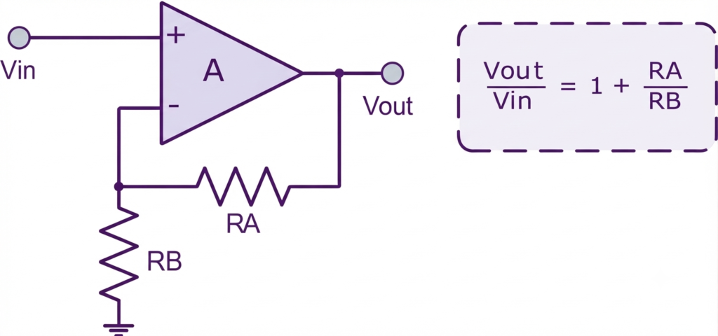
The non-inverting operational amplifier amplifies the input signal without reversing its phase. The input voltage is applied directly to the non-inverting (+) input, while the feedback resistor network determines the overall voltage gain.
The voltage gain is determined by the ratio of the feedback resistors and can be expressed as:
or, equivalently:
Since the input and output signals remain in phase, the non-inverting amplifier is widely used for voltage amplification, signal conditioning, and impedance matching.
The Basic Op-amp Building Blocks Non-inverting Amplifier
The Inverting Amplifier
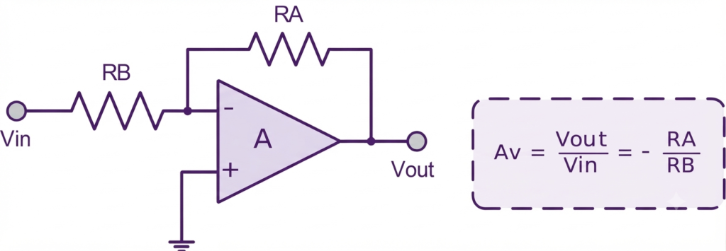
The inverting operational amplifier is a common op-amp configuration that both amplifies and reverses the phase of the input signal. The input voltage is applied to the inverting (−) input through the input resistor , while the feedback resistor connects the output back to the inverting input.
Negative feedback determines the closed-loop voltage gain, which is given by the ratio of the feedback and input resistances:
The negative sign indicates a 180° phase reversal between the input and output signals. By selecting suitable values of and , the required voltage gain can be obtained.
The Inverting Op-amp Circuit
The Bridge Amplifier
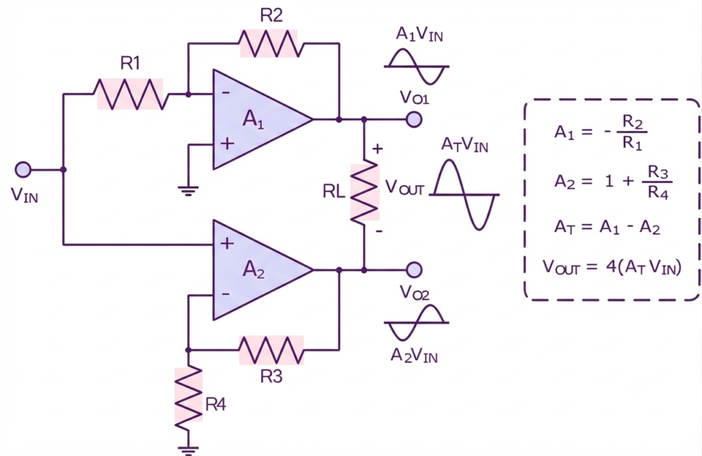
A bridge amplifier can be formed by combining inverting and non-inverting op-amp configurations. The same input signal is applied to both op-amps, while the load resistor is connected between their two output terminals.
The two amplifiers produce output signals with opposite polarities. Therefore, the voltage developed across the floating load is the difference between the two op-amp outputs.
When the magnitudes of the two amplifier gains, and , are equal, the voltage across the load is approximately twice the output voltage of either amplifier. This configuration is useful when a higher voltage swing is required across a load without increasing the individual op-amp supply voltage.
The Op-amp Building Blocks Bridge Circuit
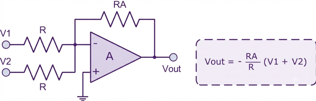
The Voltage Summing Amplifier (Adder)
The op-amp adder, commonly called a summing amplifier, is an important Op-Amp Building Block that combines two or more input voltages to produce an output proportional to their sum. In the standard inverting configuration, the resulting output has the opposite polarity to the applied inputs.
Multiple input signals can be summed by adding more input branches to the circuit. When the input resistors have equal values, such as , each input contributes equally to the output.
For unequal input resistors, the circuit produces a weighted sum, where each input is scaled according to its resistor value. The output voltage is given by:
The negative sign indicates that the output is inverted relative to the input signals. By selecting different input resistor values, the contribution of each input voltage can be controlled independently.
The Op-amp Building Blocks Voltage Adder
The Differential Amplifier (Subtractor)
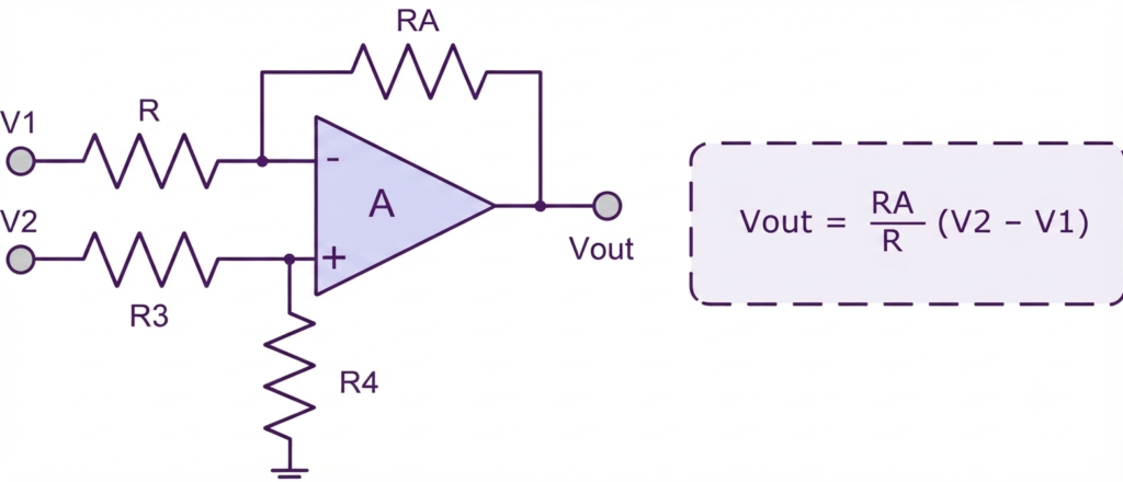
The op-amp subtractor, also known as a differential amplifier, is an important Op-Amp Building Block that uses both the inverting and non-inverting inputs. It produces an output voltage proportional to the difference between two input voltages, and , allowing one signal to be subtracted from another.
Additional input stages can be included when more complex subtraction or differential signal processing is required.
When the resistor pairs are matched, such that and , the circuit provides unity differential gain. For unequal resistor values, the voltage gain depends on the resistor ratios.
The output polarity depends on the relative values of the two input voltages. When is greater than , the output is negative for the polarity convention shown. When is less than , the output becomes positive. This makes the differential amplifier useful for signal subtraction, measurement, and differential signal processing.
The Op-amp Building Blocks Voltage Subtractor
Op-Amp Comparator
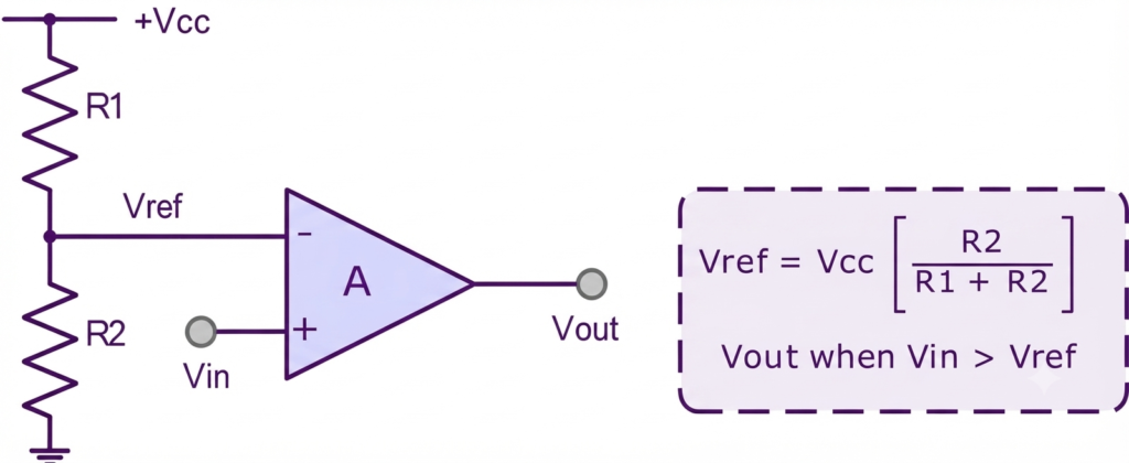
The op-amp comparator is an important Op-Amp Building Block used to compare an input voltage with a predetermined reference voltage. It switches its output state when the input crosses the reference level.
When the input voltage becomes greater than the reference voltage,
the comparator changes its output state. When the input falls below the reference voltage,
the output switches back to the opposite state.
A basic comparator can also use positive feedback to introduce hysteresis. This configuration is known as a Schmitt trigger and helps prevent unwanted rapid switching when the input signal is close to the threshold voltage.
The Op-amp Building Blocks Comparator Circuit
The circuits discussed above demonstrate how an operational amplifier can be configured for different analog signal-processing functions. By changing the feedback and input components, the same basic op-amp can perform amplification, buffering, summing, subtraction, and voltage comparison.
These Op-Amp Building Blocks form the foundation for designing more advanced analog electronic circuits.
Conclusion
Op-Amp Building Blocks provide the foundation for designing a wide range of analog electronic circuits. By using suitable input and feedback components, an operational amplifier can be configured for amplification, buffering, summing, subtraction, signal comparison, and other signal-processing functions. Understanding these basic configurations makes it easier to analyze and design more advanced operational amplifier circuits.
Read Next:
- Operational Amplifier (Op-Amp): Basics, Types, Working & Applications
- Non-inverting Operational Amplifier: Circuit, Gain & Formula
- Inverting Operational Amplifier: Circuit, Gain and Working
- Inverting vs Non-Inverting Amplifier
- Summing Amplifier: Circuit, Formula, Derivation & Applications
- Differential Amplifier: Circuit, Types, Formula & Applications
- Op-Amp Integrator Amplifier: Formula, Working & Applications
- Op-Amp Multivibrator: Working, Circuit, Types & Applications
- Op-Amp Comparator: Circuit, Working, Formula, Hysteresis & Applications
- Op-Amp Monostable Multivibrator: Circuit, Working, Formula & Timing