A full wave rectifier is a crucial device in power supply systems, converting alternating current (AC) into direct current (DC). Learn about its definition, types, and working principles in this detailed guide.
Rectifiers are vital in converting alternating current (AC) into direct current (DC), and the full wave rectifier is one of the most efficient ways to achieve this. It ensures both the positive and negative cycles of AC are utilized, providing a smooth and continuous DC output. In this guide, we’ll explore what a full wave rectifier is, its types, and how it works in an electrical system.
What is a Full Wave Rectifier?
A full wave rectifier is an electronic device that converts the entire input of an alternating current (AC) into a unidirectional direct current (DC). Unlike a half-wave rectifier, which only works on one half of the AC cycle, a full wave rectifier processes both the positive and negative halves of the AC signal. This results in a more efficient and consistent DC output.
Essentially, while the AC voltage naturally alternates, the full wave rectifier redirects the current flow in such a way that the output voltage remains unidirectional, providing smoother power.
Types of Full Wave Rectifiers
Full wave rectifiers come in two main configurations:
- Center-Tap Full Wave Rectifier
- Bridge Full Wave Rectifier
1. Center-Tap Full Wave Rectifier
The center-tap full wave rectifier uses a transformer with a center tap in its secondary winding. This center tap creates two equal halves of the input AC signal. The circuit typically involves two diodes: one diode conducts during the positive cycle, and the other during the negative cycle of the AC input.
- Characteristics:
- Requires a transformer with a center tap.
- Only two diodes are needed for operation.
- The output voltage is half of the total input voltage since it only uses one-half of the transformer at a time.
2. Bridge Full Wave Rectifier
The bridge full wave rectifier consists of four diodes arranged in a bridge configuration. It does not require a center-tap transformer, making it more commonly used. During the positive half of the AC cycle, two diodes conduct current, and during the negative half, the other two diodes take over. This ensures both halves of the AC waveform are used.
- Characteristics:
- No need for a center-tap transformer.
- Four diodes are used in the circuit.
- It allows the full AC voltage to be rectified into DC without halving the voltage.
How Does a Full Wave Rectifier Work?
Understanding the working principle of a full wave rectifier starts with observing its behavior during the two halves of the AC signal.
Working of Centre tapped full wave Rectifier
The working of a center-tapped full wave rectifier involves two main phases—during the positive half cycle and the negative half cycle of the AC input.
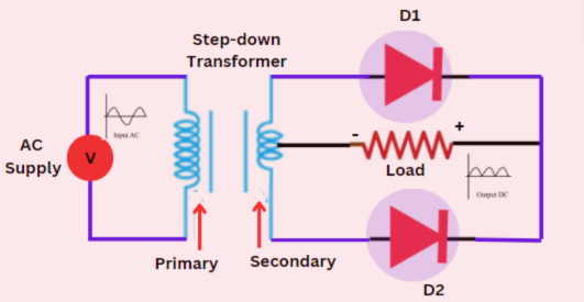
1. Positive Half Cycle
- During the positive half of the input AC cycle, the upper half of the transformer secondary winding is positive, and the lower half is negative.
- Diode D1 becomes forward-biased because the anode of D1 is connected to the positive voltage from the upper half of the transformer. As a result, D1 conducts current.
- Diode D2 is reverse-biased during this cycle because the anode is connected to the negative voltage of the lower half of the transformer, so D2 remains off.
- The current flows through D1 and passes through the load resistor in one direction, resulting in a positive output voltage across the load.
2. Negative Half Cycle
- During the negative half of the AC input cycle, the polarities of the transformer’s secondary winding reverse: the lower half becomes positive, and the upper half becomes negative.
- Diode D2 now becomes forward-biased as its anode is connected to the positive voltage from the lower half of the transformer, so D2 conducts.
- Diode D1, on the other hand, becomes reverse-biased and does not conduct.
- The current now flows through D2 and again through the load resistor in the same direction, resulting in a positive output voltage across the load.
Output Waveform
As both the positive and negative halves of the AC input are used, the output waveform is continuous but pulsating DC. The voltage across the load resistor does not change direction, and both diodes alternately conduct during each half cycle of the AC input. The result is that the entire AC signal is converted into a unidirectional DC signal.
Filtering the Output
To smooth the pulsating DC output, a filter capacitor can be added to the circuit. The capacitor charges during the peaks of the rectified output and discharges when the voltage drops, thus smoothing the waveform and producing a more stable DC voltage.
Working of full wave Bridge Rectifier
The operation of a full wave bridge rectifier can be broken down into two phases corresponding to the positive half cycle and the negative half cycle of the input AC signal.
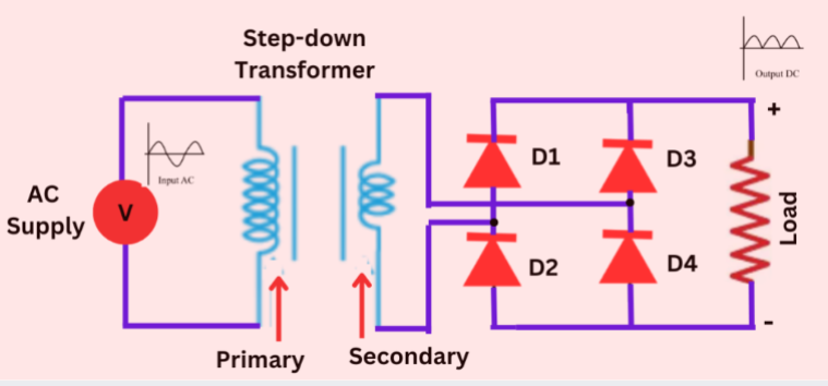
1. Positive Half Cycle
- During the positive half of the AC input, the input terminal connected to the anode of Diode D3 becomes positive, and the terminal connected to the anode of Diode D2 becomes negative.
- Diodes D3 and D2 are forward biased, meaning they allow current to pass through them because their anodes are connected to the positive AC voltage and their cathodes are connected to the load.
- Diodes D1 and D4, on the other hand, are reverse-biased during this cycle, so they block the current from flowing through them.
- As the current flows through D1 and D2, it passes through the load resistor in one direction, creating a positive output voltage across the load.
2. Negative Half Cycle
- During the negative half of the AC input, the polarity of the input voltage reverses: the terminal connected to the anode of D3 becomes negative, and the terminal connected to the anode of D1 becomes positive.
- Now, Diodes D1 and D4 become forward-biased, allowing current to pass through them, while Diodes D2 and D3 become reverse-biased and block the current.
- The current flows through D1 and D4, again in the same direction through the load resistor as in the positive half cycle.
- This ensures that even during the negative half of the AC cycle, the current flows in a single direction through the load, maintaining a positive output voltage.
Output Waveform:
The output from the bridge rectifier is a pulsating DC signal, as both the positive and negative halves of the AC signal are rectified to produce a continuous DC output. The direction of current flow through the load remains the same during both halves of the AC cycle.
Smoothing the Output:
Although the output is DC, it still contains ripples due to the pulsating nature of the waveform. To reduce these ripples and obtain a smoother DC voltage, a filter capacitor can be used. The capacitor charges during the peaks of the pulsating DC and discharges during the valleys, effectively smoothing the output and providing a more stable DC signal.
Advantages of Full Wave Rectifiers
- Better Efficiency: Since the full AC signal is converted to DC, full-wave rectifiers are significantly more efficient compared to half wave rectifiers.
- Reduced Ripple Voltage: The output ripple is lower, meaning less fluctuation in the DC signal, which results in better performance in powering devices.
- Higher Average Output Voltage: Full-wave rectifiers produce a higher average DC voltage than half-wave rectifiers, making them more effective for a range of applications.
- Improved Power Utilization: By utilizing both halves of the AC input, the full wave rectifier maximizes power conversion efficiency.
Applications of Full Wave Rectifiers
Full wave rectifiers are frequently used in various electronic devices and systems where a stable and continuous DC supply is needed. Here are some of the common applications:
- Power Supplies for Electronics: Almost all power supplies, especially in home appliances and electronic devices, use full wave rectifiers to convert the mains AC into usable DC.
- Radio Receivers: Full wave rectifiers help in demodulating radio signals by converting AC signals into usable DC.
- Battery Charging: Since batteries require DC for charging, full wave rectifiers are ideal in battery charging circuits for their efficiency and smooth output.
- DC Motor Drives: Many industrial applications rely on DC motors, and full wave rectifiers are used to provide the required steady DC supply.
Conclusion
In summary, a full-wave rectifier is an essential component in many electronic circuits, providing a more efficient and smoother DC output than half-wave rectifiers. Whether you’re using a center-tap configuration or a bridge design, the full wave rectifier ensures better power conversion and reliability for a wide range of applications. Understanding how these rectifiers work can help you design more efficient power supply systems or improve existing ones for industrial or personal electronics use.