Zener diode applications are widely seen in electronic circuits for voltage regulation, meter protection, wave shaping, noise reduction, overvoltage protection, voltage reference, temperature sensing, and current limiting. Learn how these diodes help stabilize voltage, protect meters, modify waveforms, suppress noise, sense temperature variations, and limit current flow in various applications.
In this article, we will explain the basic principle and operation of Zener diodes and explore Zener diode applications in detail.
What is a Zener Diode?
A Zener diode is a specialized semiconductor device that operates in reverse bias mode, maintaining a stable voltage across its terminals. Unlike conventional diodes, which block reverse current, Zener diodes allow current flow when the reverse voltage exceeds a specific value known as the Zener voltage, making them useful in voltage regulation applications.
Every diode has a breakdown voltage, the minimum reverse voltage needed to allow significant current in the opposite direction. In conventional diodes, exceeding this voltage can cause damage. However, Zener diodes are designed to function reliably in breakdown mode, ensuring a controlled voltage drop without harming the device, making them highly efficient.
When the reverse voltage applied to a Zener diode reaches its Zener voltage, the diode starts conducting in reverse, ensuring a stable voltage. This property is essential in circuits requiring consistent voltage regulation. The diode maintains a fixed voltage despite input variations, making it ideal for power supplies and voltage reference circuits.
The Zener voltage depends on factors like doping level and p-n junction thickness. Higher doping levels lead to lower breakdown voltages, while thicker p-n junctions result in higher breakdown voltages. These properties allow engineers to design Zener diodes with precise voltage ratings for specific electronic applications requiring stable and controlled voltage operation.
Zener diodes exhibit two primary breakdown mechanisms: the Zener effect and the avalanche effect. The Zener effect occurs in diodes with low breakdown voltages, where quantum tunneling allows current flow. The avalanche effect dominates at higher voltages, where high electric fields accelerate charge carriers, causing impact ionization and sustaining the reverse current.
In forward bias mode, a Zener diode behaves like a standard diode, allowing current flow when the voltage exceeds approximately 0.7V. In reverse bias mode, it remains non-conductive until the reverse voltage reaches the Zener voltage. Once breakdown occurs, the diode maintains a constant voltage while allowing controlled current flow.
When the reverse voltage is below the Zener voltage, the diode blocks current like an open circuit. If the voltage equals or exceeds the Zener voltage, the diode enters breakdown mode, regulating voltage despite fluctuations. This characteristic is widely used in power regulation circuits, ensuring stable voltage outputs in variable input conditions.
A major advantage of Zener diodes is their ability to function as constant voltage sources, keeping output voltage stable despite input variations. This makes them crucial for applications like surge protection, voltage regulation, and waveform shaping in electronic circuits. Their reliable performance makes them essential components in modern electronic design and power management.
Zener Diode as a Voltage Regulator
One of the most common Zener diode applications is as a voltage regulator or stabilizer, ensuring a constant output voltage despite variations in input voltage or load conditions.

A Zener diode is widely used as a voltage regulator to provide a stable voltage output even when the input voltage varies. A voltage regulator ensures that a circuit receives a constant voltage, which is essential for the proper functioning of electronic devices. This makes Zener diodes useful in power supply circuits.
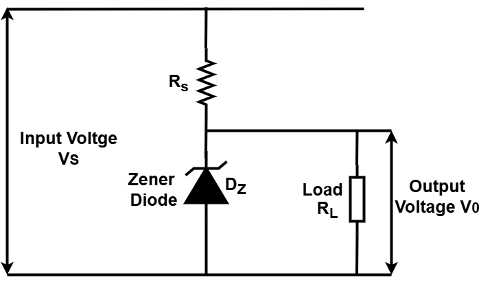
In a voltage regulator circuit, a series resistor (RS) is connected in series with the Zener diode (DZ) to limit the current. The load resistor (RL) represents the circuit or device that needs a stable voltage supply. The input voltage (VS) may fluctuate, but the output voltage (VO) remains steady at the Zener voltage (VZ).
When the input voltage (VS) is lower than the Zener voltage (VZ), the Zener diode does not conduct, and the output voltage (VO) equals the input voltage. As the input voltage reaches the Zener voltage, the diode begins to conduct in reverse bias mode, maintaining a constant output voltage equal to VZ. If the input voltage rises above the Zener voltage, the diode continues to conduct more current while maintaining the output voltage at VZ. The excess voltage is dissipated as heat in the series resistor (R S).
The series resistor (R S) is crucial in the circuit and can be calculated using Ohm’s law:
RS = (VS – V Z) / IZ
Here, IZ is the minimum current required for the Zener diode to stay in breakdown mode. This value is usually provided in the diode’s datasheet. The resistor must be chosen carefully to handle power dissipation without overheating, ensuring stable operation.
Using a Zener diode as a voltage regulator has several advantages. It is a simple, cost-effective, and easy-to-implement solution for voltage regulation. By selecting Zener diodes with different breakdown voltages, various output voltage levels can be achieved. This method works well for low-power applications where minor voltage fluctuations can be tolerated.
However, there are also some limitations. The circuit is not highly efficient because power is lost as heat in the series resistor (RS). Load regulation is not ideal since changes in the load resistance (RL) affect the Zener current (IZ), which can slightly alter the output voltage. Line regulation is also limited because variations in the input voltage influence the current through the diode. Additionally, the output current capacity is restricted by the maximum power rating of the Zener diode, making it unsuitable for high-current applications.
Despite its limitations, a Zener diode remains a reliable and widely used voltage regulation method in small electronic circuits, providing a simple way to maintain a stable voltage supply.
Zener Diode for Meter Protection

A Zener diode is also used as a meter protector to prevent electrical meters, such as ammeters, voltmeters, and ohmmeters, from damage due to accidental overloads or polarity reversals. The meter protection circuit typically includes one or more Zener diodes connected in parallel with the meter movement to limit excess current flow.
In this circuit, an ammeter (M) measures the current (I) flowing through the load resistor (RL). Two identical Zener diodes (D1 and D2) are used, each having a Zener voltage equal to half the maximum allowable meter deflection (VM). The series resistors (R S1 and R S2) control the current passing through D1 and D2, ensuring stable operation.
The circuit functions based on the input current. When the current (I) is below the threshold (V M / R M), where R M is the meter’s internal resistance, the Zener diodes remain inactive, allowing normal meter deflection according to Ohm’s law. When the current exceeds this threshold, one of the Zener diodes starts conducting while the other remains blocked, depending on the polarity of the current.
For example, if the current (I) is positive and exceeds the threshold, D2 starts conducting while D1 blocks. This allows most of the current to bypass the meter through D2, limiting the meter deflection to V M and protecting it from overload. If the current is negative beyond the threshold, D1 conducts while D2 blocks, directing excess current through D1 and preventing polarity reversal damage.
Using a Zener diode for meter protection has several benefits. It is a simple, cost-effective solution that effectively safeguards meters from overload and polarity reversals. It works with both AC and DC currents by utilizing two identical Zener diodes, making it versatile for various applications.
However, there are some drawbacks. The presence of Zener diodes introduces minor errors in meter readings due to their nonlinearity. Meter sensitivity is slightly reduced because of the shunting effect of the diodes. Additionally, selecting appropriate values for the Zener voltage (V Z) and series resistors (R S1 and R S2) is essential for accurate protection without affecting normal meter operation.
Despite its limitations, a Zener diode-based meter protector remains a reliable and widely used method to prevent damage to sensitive measuring instruments, ensuring their longevity and accuracy.
Zener Diode as a Wave Shaper
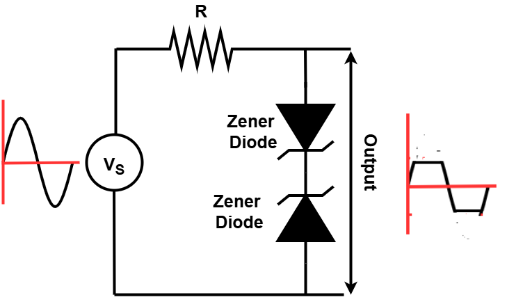
A Zener diode can also be used as a wave shaper to modify an input waveform into a different shape. A wave shaper typically includes nonlinear components such as resistors, capacitors, inductors, or diodes. In this circuit, Zener diodes help convert a sinusoidal waveform into a square waveform.
The circuit includes a capacitor (C) that blocks DC components while allowing AC signals to pass. A load resistor (R L) represents the device that requires a square wave input. A sinusoidal voltage source (V S) provides an input signal with a peak amplitude greater than the Zener voltage. The output voltage (V O) is taken across R L and is shaped into a square wave.
The circuit operates by limiting the output voltage. During the positive half-cycle of V S, when the voltage across the Zener diodes (D1 and D2) is below their breakdown voltage, they offer high resistance and block current flow. The input voltage appears at the output unchanged. When the positive peak of V S exceeds the Zener voltage, D1 starts conducting in reverse bias, clamping the output voltage to V Z. The excess voltage (V S – V Z) is dropped across the series resistor (R S).
During the negative half-cycle of V S, the diodes again remain inactive when the voltage is below the Zener breakdown voltage. The input voltage appears unchanged at the output. When the negative peak of V S exceeds the Zener voltage, D2 conducts in reverse bias, clamping the output voltage to -V Z. The excess voltage (-V S + V Z) is again absorbed by R S.
Using a Zener diode as a wave shaper has several advantages. It is a simple and cost-effective method to convert sine waves into square waves. The output amplitude can be adjusted by selecting different Zener voltages. The circuit works with both AC and DC input voltages when two identical Zener diodes are used.
However, there are some limitations. The non-linearity of the Zener diodes introduces distortion and noise in the output waveform. The clipping effect of the diodes reduces the amplitude of the input signal. The proper selection of Zener voltage (V Z), series resistor (R S), and capacitor (C) is necessary to ensure stable and efficient operation.
Despite its drawbacks, this method remains useful for generating square waves from sinusoidal signals in low-power applications.
Noise Reduction
Zener diodes play a crucial role in noise-reduction applications. They are commonly used in circuits to suppress high-frequency noise. By connecting Zener diodes in parallel with the load, they effectively shunt unwanted high-frequency noise to the ground. This process helps minimize noise voltage across the load, ensuring cleaner signal transmission and improved circuit performance.
Overvoltage Protection
Overvoltage occurs when the voltage exceeds a specified threshold, potentially damaging sensitive electronic components. Zener diodes are widely used for overvoltage protection in circuits. When the voltage surpasses a predefined limit, the Zener diode conducts and clamps the voltage to its Zener voltage, preventing further rise. It safely diverts the excess current away from the protected components, ensuring circuit stability and protection.
Voltage Reference
One of the key Zener diode applications is serving as a voltage reference in electronic circuits. In analog circuits, Zener diodes provide a stable reference voltage essential for precise operations. By connecting a Zener diode in series with a resistor, a consistent and reliable reference voltage is generated. This stable voltage helps regulate circuit performance, ensuring accuracy and reliability in various electronic applications.
Zener Diode for Temperature Sensing
While Zener diodes are primarily used for voltage regulation, they can also function as temperature sensors. This is possible because their breakdown voltage varies with temperature due to their temperature coefficient. By monitoring these voltage changes, temperature variations can be detected. However, Zener diode-based temperature sensing faces challenges such as limited sensitivity, non-linearity, and accuracy constraints, making it less common compared to dedicated temperature sensors.
Zener Diode for Current Limiting
Zener diodes are also used for current limiting in various applications. To achieve this function, a Zener diode is connected in series with the load. When the load attempts to draw excessive current, the Zener diode responds by reducing the voltage across it, thereby restricting the current flow. This helps protect electrical components and appliances from potential damage due to overcurrent conditions.
Conclusion
Zener diode applications play a crucial role in electronics, including voltage regulation, circuit protection, current limiting, temperature sensing, voltage reference, overvoltage protection, and waveform shaping. Their ability to maintain a stable voltage in reverse breakdown mode makes them ideal for use in power supplies, meter protection, and signal processing. These applications help regulate voltage fluctuations, protect sensitive components, and shape waveforms by clipping excess voltage.
When designing circuits with Zener diodes, factors such as power dissipation, temperature variations, and load changes must be considered. Choosing the right diode based on its Zener voltage (VZ), power rating (PZM), and impedance (ZZ) ensures efficient performance and long-term reliability. Proper circuit design helps optimize Zener diode applications, minimizing power losses and maintaining stability in electronic systems.
Read Next: