A differential amplifier is an important building block in op-amp circuits and many analog electronic systems. It is widely used where two input signals need to be compared or processed based on their relative voltage levels. Its ability to respond to changes between the input signals makes it useful in signal conditioning, measurement, instrumentation, and other applications.
What Is a Differential Amplifier?
A differential amplifier is an analog circuit designed to process two input voltages, and , and produce an output based on the voltage difference between them. It is also commonly called a difference amplifier or op-amp subtractor. An important characteristic of this circuit is its ability to amplify the difference between the inputs while rejecting signals that are common to both.
For an ideal differential amplifier, the output voltage can be expressed as:
where:
- is the output voltage.
- and are the two input voltages.
- is the differential gain of the amplifier.
The equation shows that the output depends only on the difference between the two input signals. When and have the same voltage, their difference is zero, so the ideal output is also zero. When the input voltages differ, the amplifier produces an output whose magnitude is determined by the differential gain .
This differential operation makes the circuit useful for comparing signals and rejecting unwanted voltage components that appear simultaneously at both inputs.
Differential Amplifier Formula Derivation
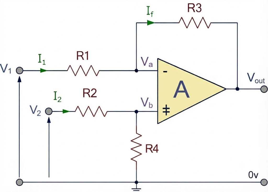
By applying the superposition principle and connecting each input to 0 V (ground) one at a time, the contribution of each input to the output voltage can be determined. Combining these individual contributions gives the transfer function of the differential amplifier circuit:
At summing Point:
and.
If V2=0, then,
If V1=0, then,
Therefore,
This equation represents the general transfer function for a two-input, op-amp-based differential amplifier.
When the corresponding resistor pairs are selected with equal values, such that and , the transfer function can be simplified considerably. Under these matched-resistor conditions, the circuit equation reduces to the following expression:
Differential Amplifier Circuit
There are two main types of differential amplifier circuits:
- BJT Differential Amplifier – This type of differential amplifier uses transistors, such as Bipolar Junction Transistors (BJTs) or Field Effect Transistors (FETs), to amplify the difference between two input signals.
- Op-Amp Differential Amplifier – This differential amplifier is designed using Operational Amplifiers (op-amps) and is commonly used as a voltage subtractor.
The basic BJT and op-amp differential amplifier circuits are shown below.
BJT Differential Amplifier
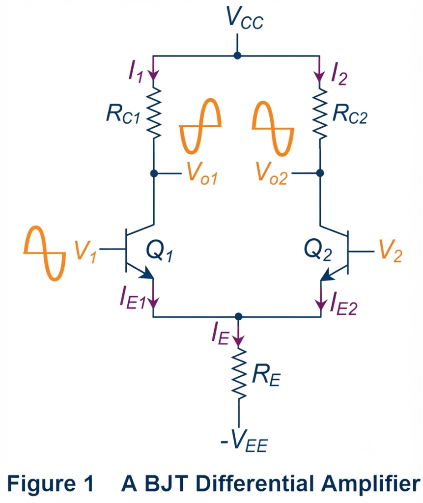
Figure 1 shows a basic BJT differential amplifier circuit consisting of two BJTs, Q1 and Q2, along with two oppositely polarized power supplies, VCC and –VEE. The circuit uses three resistors: two collector resistors, RC1 and RC2, connected to the respective transistors, and a common emitter resistor, RE, shared by both transistors.
Here, the input signals V1 and V2 are applied to the bases of Q1 and Q2, respectively, while the output signals are obtained from their collector terminals, Vo1 and Vo2.
When a sinusoidal input signal V1 is applied to the base of Q1 and its voltage increases, Q1 conducts more heavily. As a result, its collector current IC1 increases, producing a greater voltage drop across collector resistor RC1. This causes the collector output voltage Vo1 to decrease.
At the same time, the increase in emitter current IE1 raises the total common-emitter current IE. This produces a larger voltage drop across the common emitter resistor RE.
As the emitter voltage changes, the base-to-emitter voltage of Q2 is reduced. Consequently, the collector current IC2 decreases. The lower current through collector resistor RC2 reduces its voltage drop and causes the output voltage Vo2 to increase.
Therefore, the sinusoidal variation applied to Q1 produces corresponding changes at the collector of Q2. The outputs at the two collector terminals vary in opposite directions, giving a 180° phase difference between Vo1 and Vo2.
The differential output can be obtained by measuring the voltage difference between the collector terminals of Q1 and Q2. This arrangement allows the BJT differential amplifier to amplify the difference between its two input signals.
Op-Amp Differential Amplifier
An op-amp differential amplifier can be configured to operate as a subtractor amplifier, producing an output voltage that depends on the difference between its two input signals. Ideally, the output voltage can be expressed as:
where and are the voltages applied to the inverting and non-inverting input terminals, respectively, and is the differential gain.
According to this ideal relationship, the output voltage becomes zero when the two input voltages are equal. In a practical op-amp, however, the output may not be exactly zero because the gain and circuit characteristics associated with the two inputs are not perfectly identical.
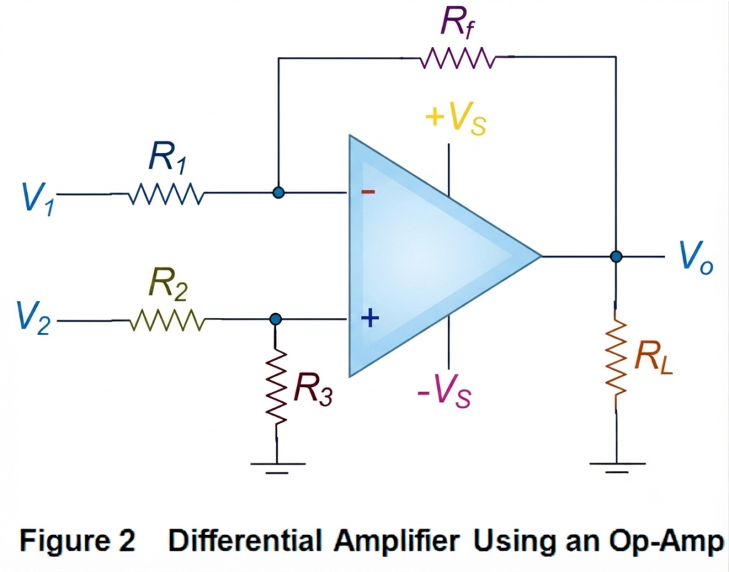
A practical differential amplifier can be designed by configuring an op-amp with an appropriate resistor network, as shown in Figure 2. This circuit combines the principles of both inverting and non-inverting amplifier configurations.
Output Voltage Equation of Differential Amplifier
The output voltage can therefore be considered as the combined effect of the outputs produced by the inverting and non-inverting sections of the op-amp circuit.
Therefore, the output voltage of the differential amplifier is the sum of the output voltages generated by the op-amp operating in the inverting and non-inverting configurations.
For a properly matched resistor network, where:
and
the output voltage becomes proportional to the difference between the two input voltages. The differential gain of the circuit is determined by the selected resistor values.
An important characteristic of a practical differential amplifier is its ability to reject signals that are common to both inputs. This performance is described by the common-mode rejection ratio (CMRR). A high CMRR allows the circuit to amplify the desired voltage difference while reducing the effect of common-mode signals and unwanted interference.
Applications of Differential Amplifier
A differential amplifier is primarily designed to respond to the voltage difference between two input signals. This characteristic makes it useful in various analog electronic and signal-processing applications. Depending on the circuit configuration, differential amplifiers can also be used in Wheatstone bridge circuits, light-activated circuits, and instrumentation systems.
Some important applications and configurations of differential amplifiers include:
- Signal subtraction: A differential amplifier can subtract one input signal from another and produce an output proportional to their voltage difference.
- Negative-feedback circuits: When used with an operational amplifier, a differential amplifier can form part of a negative-feedback circuit for controlled and stable amplification.
- Wheatstone Bridge Differential Amplifier: This configuration detects small voltage differences caused by changes in resistance within bridge circuits.
- Light-Activated Differential Amplifier: A differential amplifier uses light-sensitive devices to detect and process changes in light intensity.
- Instrumentation Amplifier: Differential amplifier principles are widely used in instrumentation amplifiers for accurately measuring small differential signals in the presence of common-mode noise.
- High-Input-Impedance Instrumentation Amplifier: This configuration provides high input impedance while amplifying small differential signals, making it suitable for measurement and signal-conditioning applications.
- Automatic Gain Control: Differential amplifiers can be used in control circuits with automatic gain adjustment to maintain a desired signal level.
- Amplitude Modulation: Differential amplifier circuits can be used in amplitude-modulation systems for processing and combining signals.
- Control and Measurement Systems: Their ability to amplify the difference between two signals makes differential amplifiers useful in instrumentation, motor and servo control, audio circuits, and analog-to-digital conversion.
Conclusion
A differential amplifier is an important analog circuit that amplifies the voltage difference between two input signals while rejecting signals common to both inputs. Its practical performance depends on factors such as differential gain, resistor matching, and common-mode rejection ratio (CMRR). Because of these characteristics, differential amplifiers support a wide range of applications, including op-amp circuits, instrumentation, signal conditioning, control systems, and other analog systems.
Read Next:
- Inverting vs Non-Inverting Amplifier: Differences, Gain, and Applications
- Inverting Operational Amplifier: Circuit, Working, and Gain Formula
- Op-Amp Building Blocks: Basic Circuits and Applications
- Operational Amplifier (Op-Amp): Basics, Types, Working & Applications
- Non-inverting Operational Amplifier: Circuit, Gain & Formula
- Summing Amplifier: Circuit, Gain Formula, Derivation & Applications
- Op-Amp Integrator Amplifier: Formula, Working & Applications