An Op-amp Differentiator Amplifier is an important analog circuit used in signal processing and waveform-shaping applications. It responds to changes in the input signal and produces an output related to the rate at which the input varies with time.
What Is an Op-amp Differentiator Amplifier?
An Op-Amp Differentiator Amplifier is an analog circuit that uses an operational amplifier and a capacitor to perform mathematical differentiation. It produces an output voltage related to the rate of change of the input signal with respect to time. This makes the circuit useful for detecting rapid changes in signals and processing time-varying waveforms.
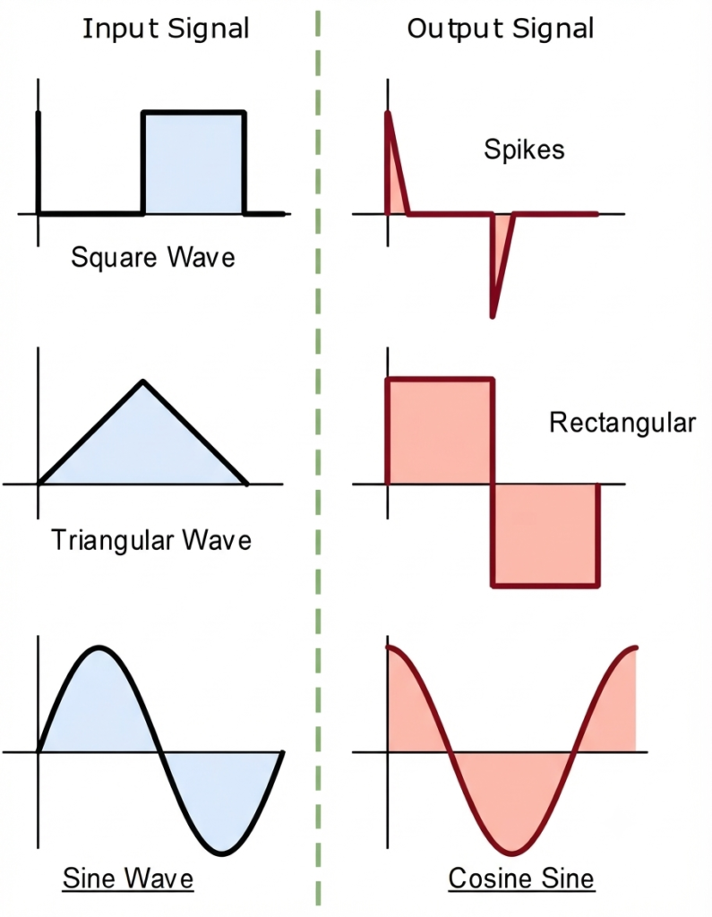
Op-amp differentiators find applications in wave-shaping circuits, signal processing, edge detection, and transient detection. For example, a differentiator can convert a triangular-wave input into a square-wave output and produce sharp pulses when the input signal changes rapidly.
Op-amp Differentiator Circuit
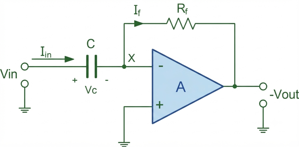
The Op-Amp Differentiator Amplifier shown above uses a capacitor C at the input and a feedback resistor connected between the op-amp output and its inverting terminal. The non-inverting terminal of the op-amp is connected to ground.
The input voltage is applied to the inverting terminal through the capacitor C. The capacitor allows an input current to flow into the inverting node, while the feedback resistor carries the feedback current from the output toward the inverting terminal. The output voltage is taken from the op-amp output.
This arrangement makes the output voltage proportional to the rate of change of the input voltage, which is the fundamental operating principle of an op-amp differentiator.
How Does The Op-amp Perform Differentiation?
The differentiation process in an Op-Amp Differentiator Amplifier is based on the frequency-dependent behavior of the input capacitor. The capacitor is connected in series with the input signal, so its reactance changes with the frequency of the applied signal.
For a constant DC input, the capacitor eventually becomes fully charged and blocks further current from reaching the op-amp’s summing point X. As a result, the steady-state output voltage becomes approximately zero.
For an AC or time-varying input, the capacitor allows current to flow. The amount of current depends on how quickly the input voltage changes. A faster change in the input produces a larger capacitor current, which results in a larger output voltage through the feedback resistor . Therefore, the output voltage is proportional to the rate of change of the input signal.
At low frequencies, the capacitive reactance is high. This limits the input current and produces a relatively small output voltage. As the frequency increases, decreases, allowing more current to flow and increasing the differentiator’s gain.
However, an ideal differentiator can become problematic at very high frequencies. As the capacitive reactance becomes very small, the circuit can provide excessive gain for high-frequency components, including noise. The limited bandwidth and phase characteristics of a practical op-amp can also cause instability or oscillation.
To improve high-frequency stability, a small capacitor is often connected in parallel with the feedback resistor . This limits the high-frequency gain and makes the practical op-amp differentiator more stable and usable over its intended frequency range.
Formula Derivation of Output Voltage of Op-amp Differentiator
Since the inverting input of the operational amplifier is at virtual ground, its voltage is approximately zero. Therefore, the current flowing through the input capacitor can be expressed as:
and,
The charge stored on a capacitor is equal to the capacitance multiplied by the input voltage:
where is the charge stored on the capacitor, is its capacitance, and is the input voltage across the capacitor.
Thus, the rate of change of the charge stored on the capacitor is:
But is the capacitor current, .
From this, the ideal output voltage of the op-amp differentiator is given as:
As we can see, the output voltage, , is equal to times the derivative of the input voltage, , with respect to time. The minus sign (–) indicates a 180° phase shift, because the input signal is applied to the inverting terminal of the operational amplifier.
Op-Amp Differentiator Waveforms
When a continuously varying waveform, such as a square wave, triangular wave, or sine wave, is applied to an Op-Amp Differentiator, the output waveform depends on the rate of change of the input signal. The shape and amplitude of the resulting output are influenced by the RC time constant of the resistor-capacitor network.
Improved Op-Amp Differentiator Amplifier
The basic Op-Amp Differentiator Amplifier, which uses a single input capacitor and a feedback resistor, has limited practical use because of its high-frequency instability and sensitivity to noise.
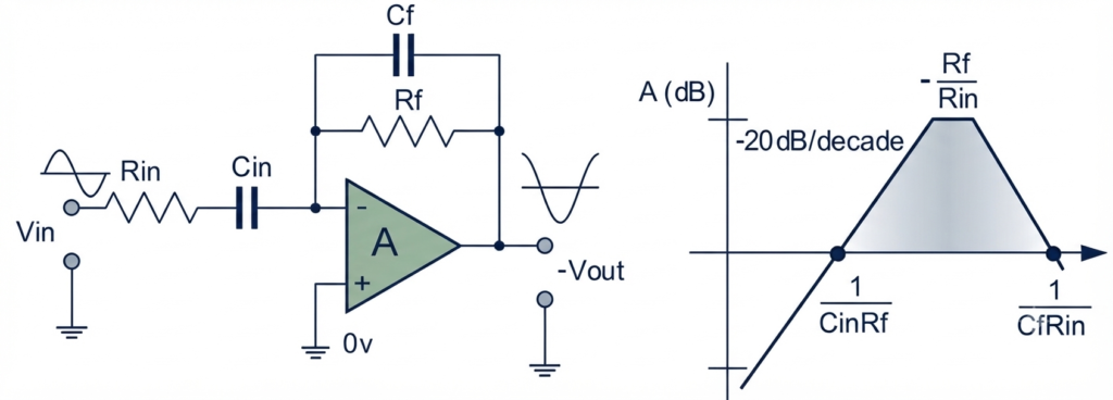
To overcome these limitations, the circuit can be modified to reduce its high-frequency gain and improve stability. An additional input resistor is connected in series with the input capacitor, as shown below. This resistor limits the current at higher frequencies and helps reduce the circuit’s sensitivity to unwanted high-frequency signals.
Adding the input resistor limits the increase in differentiator gain at higher frequencies. The maximum gain is limited to approximately . As a result, the circuit behaves more like a differentiator at low frequencies and like an op-amp amplifier with resistive feedback at higher frequencies, providing improved noise rejection.
Further attenuation of high-frequency signals can be achieved by connecting a capacitor in parallel with the feedback resistor . This additional capacitor helps control the high-frequency response and forms the basis of an active high-pass filter.
Characteristics of an Op-Amp Differentiator
An Op-Amp Differentiator Amplifier has several characteristics that determine how effectively it performs signal differentiation:
- Differentiation of input signals: The circuit produces an output voltage proportional to the rate of change of the input voltage. The output polarity is opposite to the input because the circuit uses an inverting configuration.
- Frequency-dependent operation: The input capacitor makes the circuit response dependent on frequency. Its capacitive reactance is given by . As the input frequency increases, decreases, allowing more current to flow through the capacitor.
- High-pass behavior: The ideal differentiator has a gain magnitude that increases at approximately 20 dB per decade as frequency increases. Therefore, its frequency response resembles that of a high-pass circuit.
- Phase shift: The differentiation process introduces a phase relationship between the input and output signals. For a sinusoidal input, the output is shifted by approximately .
- Waveform conversion: The circuit can perform useful waveform transformations. For example, a square-wave input produces sharp pulses, a triangular-wave input produces a square-wave output, and a sine-wave input produces a cosine-type waveform.
Limitations of an Op-Amp Differentiator
The basic Op-Amp Differentiator Amplifier has several limitations that can affect its practical performance, particularly at high frequencies:
- High-Frequency Instability – The gain of an ideal differentiator increases with frequency, which can make the circuit unstable and may lead to oscillations.
- Noise Amplification – The differentiator responds strongly to rapid signal changes, so high-frequency noise present in the input signal can also be amplified.
- Limited Bandwidth – A practical op-amp has a finite bandwidth, so the circuit cannot provide ideal differentiation over an unlimited frequency range.
- Sensitivity to Stray Signals – The capacitive input can make the circuit sensitive to unwanted high-frequency signals, interference, and harmonics.
- Output Voltage Limitation – For rapidly changing or high-frequency input signals, the output may become large enough to reach the op-amp’s supply voltage limits, causing output saturation.
- Slew-Rate Limitation – The op-amp’s finite slew rate restricts how quickly its output voltage can change, reducing differentiation accuracy for rapidly varying signals.
- Component Tolerances – Variations in the values of the resistor and capacitor can affect the circuit’s gain and frequency response.
Applications of Op-Amp Differentiator Amplifier
The Op-Amp Differentiator Amplifier is used in various analog signal-processing and waveform-shaping applications. Some common applications include:
- Edge Detection – Detects rapid changes or transitions in an input signal, making it useful for identifying the rising and falling edges of digital pulses.
- Waveform Shaping – Converts one type of waveform into another based on the rate of change of the input signal.
- Pulse Generation – Produces sharp output pulses when the input signal changes rapidly.
- Signal Processing – Used to emphasize high-frequency components and rapid variations in analog signals.
- Transient Detection – Helps detect sudden changes, spikes, and other transient events in electrical signals.
- High-Pass Filtering – A practical differentiator can be designed to attenuate low-frequency components while allowing higher-frequency signals to pass.
- Analog Computing – Used in analog circuits to perform mathematical differentiation of time-varying signals.
- Control Systems – Differentiating circuits can be used in control applications where the rate of change of an error or feedback signal needs to be detected.
Conclusion
The Op-Amp Differentiator Amplifier is an important analog circuit that produces an output proportional to the rate of change of the input signal. It can be used for wave shaping, edge detection, signal processing, and transient detection.
Although the basic differentiator provides simple mathematical differentiation, its high-frequency gain can cause noise amplification and instability. Adding an input resistor and feedback capacitor improves the circuit’s frequency response, stability, and noise rejection. These modifications make the practical differentiator more suitable for real-world signal-processing applications.
Read Next:
- Inverting vs Non-Inverting Amplifier: Differences, Gain, and Applications
- Inverting Operational Amplifier: Circuit, Working, and Gain Formula
- Op-Amp Building Blocks: Basic Circuits and Applications
- Operational Amplifier (Op-Amp): Basics, Types, Working & Applications
- Non-inverting Operational Amplifier: Circuit, Gain & Formula
- Summing Amplifier: Circuit, Gain Formula, Derivation & Applications
- Differential Amplifier: Circuit, Types, Formula & Applications
- Op-Amp Integrator Amplifier: Formula, Working & Applications