A current divider circuit consists of two or more parallel branches that provide multiple paths for electric current to flow. In a parallel circuit, the voltage across each branch is the same, while the total current divides among the branches according to their resistance. A branch with lower resistance carries more current, whereas a branch with higher resistance carries less current.
The Current Divider Rule
A current divider is a parallel circuit where the supply current splits between two or more parallel branches. Each branch provides a separate path for current, while all branches are connected across the same two nodes.
In a parallel circuit, the voltage is the same across every branch, but the current through each component can be different depending on its resistance. Therefore:
The individual branch currents can be determined easily using Ohm’s Law and Kirchhoff’s Current Law (KCL). This principle forms the basis of the current divider rule used for analyzing parallel resistor circuits.
Understanding Current Division
The simplest current divider circuit consists of two resistors connected in parallel. In this arrangement, the total current divides between the two branches according to their resistance.
The Current Divider Rule provides a quick way to calculate the current flowing through each parallel resistor as a portion of the total circuit current. It is especially useful for analyzing parallel circuits without first calculating the voltage across each resistor.
Consider the parallel resistive network below to understand how current division works.
Current Dividing Parallel Circuit
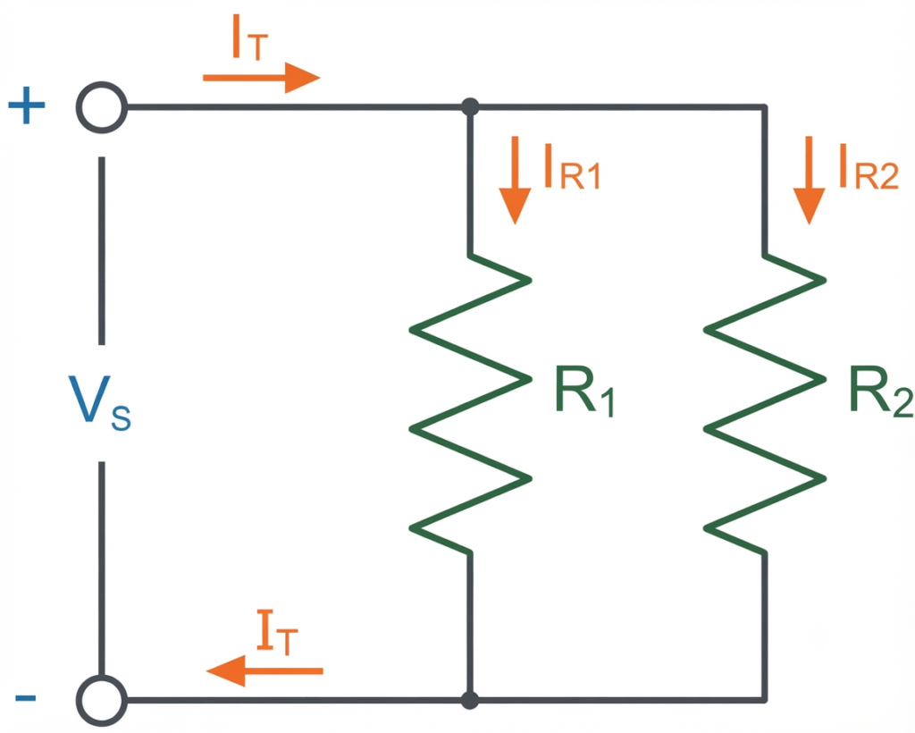
A basic current divider circuit consists of two resistors, and , connected in parallel. The source current divides at the junction into two branch currents, and , which combine again before returning to the source.
According to Kirchhoff’s Current Law (KCL), the total current entering the parallel network is equal to the sum of the branch currents:
Therefore, the current in either branch can be found from the total current and the current in the other branch:
Because and are connected in parallel, the same voltage VV appears across both resistors. Using Ohm’s Law, the branch currents can therefore be expressed as:
This common-voltage relationship forms the basis for deriving the current divider formula. Therefore, using the equivalent resistance of the two parallel resistors, the voltage across the parallel combination can be expressed as:
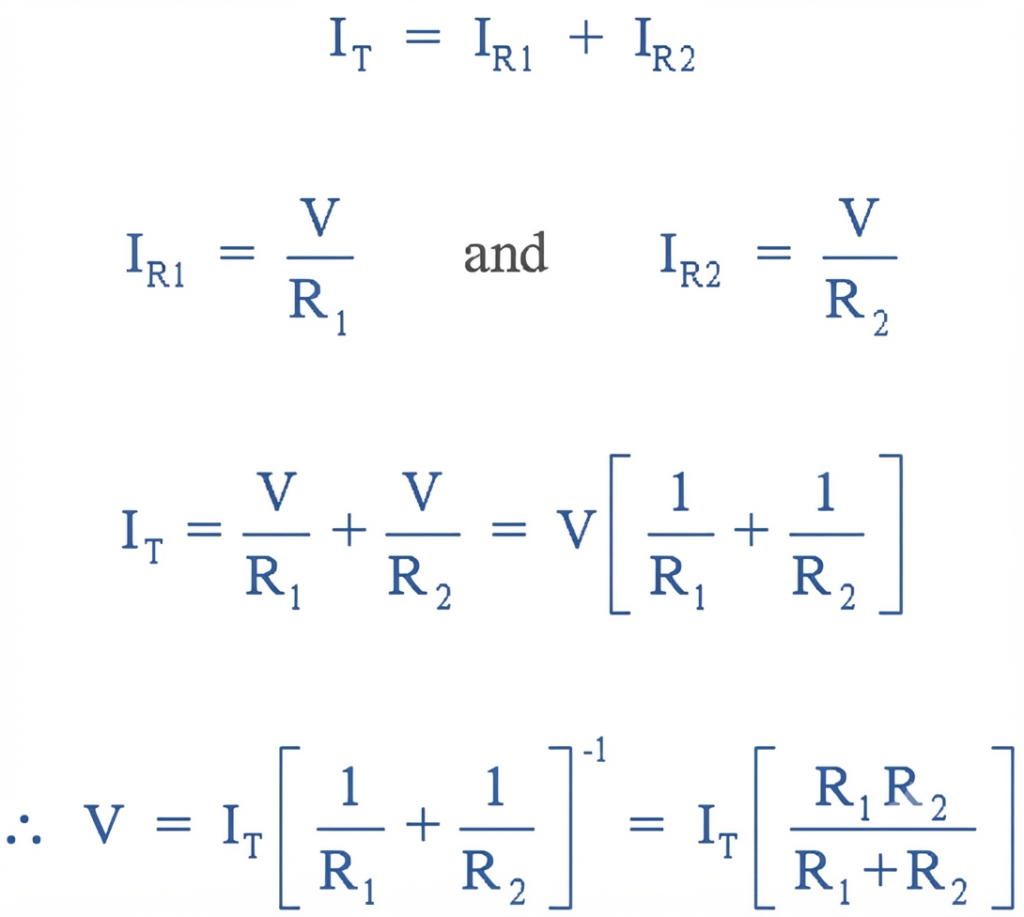
Solving for gives:
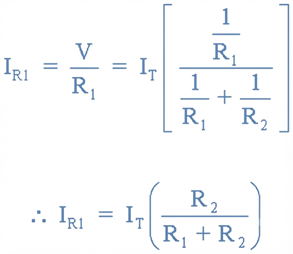
Similarly, solving for gives:
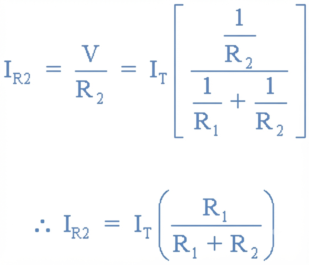
Notice that each branch-current equation contains the opposite resistor in the numerator. Thus, uses , while uses . This is because branch current is inversely proportional to resistance, so the lower-resistance branch carries the greater current.
Current Divider Worked Example No. 1
A 15 Ω resistor is connected in parallel with a 45 Ω resistor. The parallel combination is connected across a 24 V battery supply. Calculate:
- The current flowing through each resistor.
- The total current supplied by the source.
Using the values , , and :
The 15 Ω resistor carries more current than the 45 Ω resistor because current is inversely proportional to resistance. In a parallel circuit, the lower-resistance branch always carries the greater current. A short circuit with nearly zero resistance can therefore allow very high current, while an open circuit with extremely high resistance carries essentially no current.
The equivalent resistance of parallel-connected resistors is always less than the smallest individual resistance. Adding more parallel branches further reduces the equivalent resistance.
If the total current is already known, it is not always necessary to calculate every branch current. The remaining branch current can be found by subtracting the known branch currents from the total current, according to Kirchhoff’s Current Law (KCL).
Current Divider Worked Example No. 2
Three resistors are connected together to form a current divider circuit as shown below. If the circuit is supplied from a 120 V source with a power capacity of 1.8 kW, calculate the individual branch currents using the current divider rule and determine the equivalent circuit resistance.
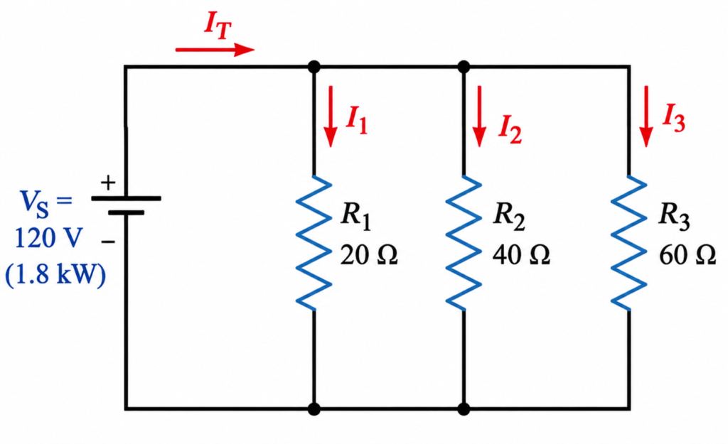
Finding Equivalent Resistance
The equivalent resistance of the three parallel resistors is first calculated as:
Therefore, the total circuit current is:
Branch currents
Using the current divider rule:
Similarly,
Therefore:
We can verify the results using Kirchhoff’s Current Law (KCL). The total current must equal the sum of the three branch currents:
This confirms our calculation. The total current is divided among the parallel branches according to their resistance values.
For a given supply voltage, adding more resistors in parallel generally increases the total supply current, because the equivalent resistance of the circuit decreases as additional current paths are added.
Current Division Using Conductances
Another useful method for finding branch currents in a DC parallel circuit is the conductance method. In a parallel network, conductance indicates how easily each branch allows electric current to flow. It is represented by the letter G and is the reciprocal of resistance.
Resistance is measured in ohms (Ω), while conductance is measured in siemens (S). The older term mho (℧) is also used for conductance; the symbol is simply an inverted ohm symbol. The siemens is the standard unit used in modern electrical engineering.
For resistors connected in parallel, the total or equivalent conductance is equal to the sum of the conductances of the individual branches. This makes the conductance method particularly convenient for analyzing current distribution in parallel circuits.
Parallel Conductance of a Current Divider
The formula of Parallel Conductance of a Current Divider is:
Conductance provides a convenient way to analyze how current is distributed among parallel branches. For example, a resistor with a resistance of 20 Ω has a conductance of 0.05 S. Because conductance and resistance are reciprocals, a higher conductance corresponds to lower resistance, while a lower conductance corresponds to higher resistance.
Conductance can also be expressed using SI prefixes such as millisiemens (mS), microsiemens (μS), and nanosiemens (nS). For example, a 20 kΩ resistor has a conductance of 50 μS.
This relationship also allows the current divider rule to be expressed using conductance instead of resistance, providing another convenient method for calculating individual branch currents.
Using Ohm’s Law, current is expressed as voltage divided by resistance. Since conductance is the reciprocal of resistance, the branch current can instead be expressed as the product of voltage and conductance:
For a parallel resistive network, the same voltage is present across every branch. Therefore, the total supply current depends on the combined conductance of all the parallel branches.
Because voltage can also be expressed in terms of current and conductance, we can write:
Using these relationships, the current divider rule can be expressed in terms of conductance rather than resistance .
Current Divider Rule using Conductance
Similarly, the currents through the parallel resistors and can be expressed as:
Unlike the resistance-based current divider equations, the same branch conductance appears in the numerator of each conductance-based equation. Thus, is calculated using , while is calculated using . This is because conductance is the reciprocal of resistance, so a higher conductance corresponds to a lower resistance and a greater share of the total current.
Current Dividers Worked Example No3
Using the conductance method, calculate the individual branch currents , , and in the following parallel resistive circuit.
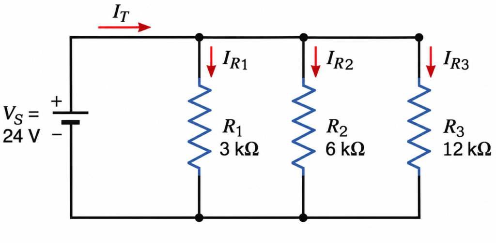
Total conductance
Total supply current
Individual branch currents
Since conductance is the reciprocal of resistance, the equivalent resistance of the example circuit can be obtained by taking the reciprocal of the total conductance:
This value is lower than the smallest resistor, , as expected for resistors connected in parallel.
Conclusion
A current divider is a parallel circuit in which the total current divides among the individual branches, while the same voltage is present across each parallel element. Kirchhoff’s Current Law (KCL) states that the total current entering a junction is equal to the sum of the currents leaving it.
When two parallel resistors have the same resistance, the total current divides equally between them. When their resistance values are different, the branch with lower resistance carries more current, while the branch with higher resistance carries less.
For circuits with three or more parallel branches, the equivalent resistance can be used along with the total current to determine the current in each branch. The current distribution depends on the inverse of the branch resistance, and the total current is the sum of all branch currents.
The conductance method provides another convenient approach for current division. Since conductance is the reciprocal of resistance, the total conductance of a parallel network is the sum of the individual branch conductances. Conductance is measured in siemens (S) and can be used to analyze current division in both DC and AC circuits.
Read Next:
- Resistors in Parallel – Parallel Connected Resistors Explained
- Resistors in Series: Definition, Formula, Rules, Calculation, and Examples
- Capacitors in Series and Series Capacitor Circuits – Complete Guide
- Voltage Divider: Rule, Equations, Formulas, and Practical Applications
- AC Capacitance: Formula, Reactance & Phase Angle
- Non-inverting Operational Amplifier: Circuit, Gain & Formula