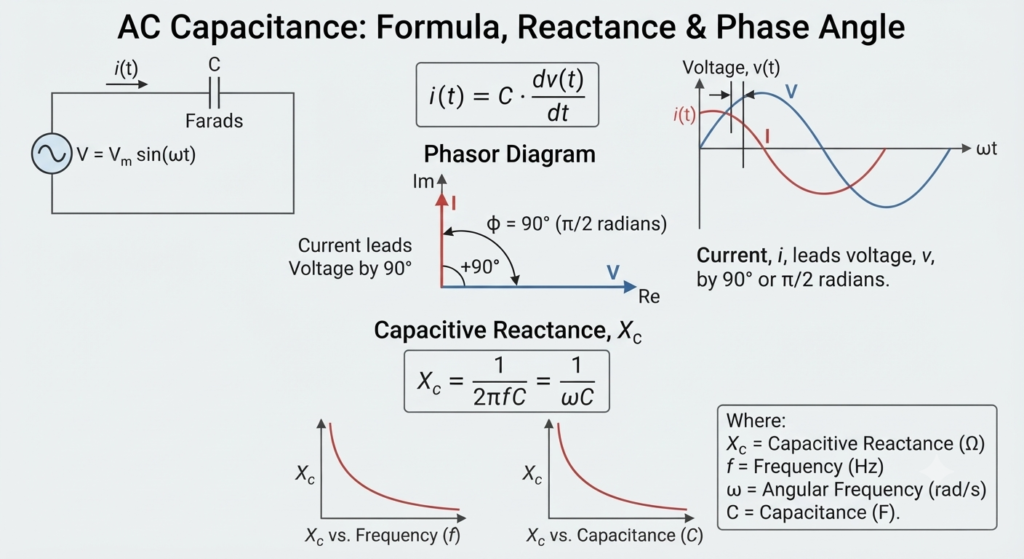
AC Capacitance describes the behaviour of a capacitor in an alternating current (AC) circuit, where it continuously charges and discharges as the supply voltage changes. In an ideal capacitor, this produces a 90° phase difference between the current and voltage waveforms.
A capacitor stores electrical energy on its conductive plates in the form of an electric charge. The charge stored by a capacitor is directly proportional to the voltage across its plates. Therefore, AC capacitance represents the ability of a capacitor to store electric charge when connected to a sinusoidal AC supply.
When a capacitor is connected to a DC voltage source, it charges toward the applied voltage at a rate determined by the circuit time constant. Once fully charged, it can retain the stored charge as long as the supply and circuit conditions allow.
During charging, a current flows into the capacitor. The capacitor opposes changes in the voltage across its plates, and the current depends on the rate of change of charge. Thus, a capacitor naturally resists changes in voltage while allowing current to flow as its stored charge changes.
The Current Through a Capacitor
The relationship between the instantaneous current through a capacitor and the rate of change of its supply voltage can be expressed mathematically as:
where is the instantaneous current in amperes, is the capacitance in farads, and represents the rate of change of voltage with time in volts per second (V/s).
When a capacitor becomes fully charged, it no longer accepts additional charge under a steady DC voltage and acts as a temporary storage device. The amount of charge stored depends on its capacitance and the applied voltage.
The charge stored by a capacitor is given by:
Since capacitance remains constant for a given capacitor, increasing or decreasing the applied voltage correspondingly changes the amount of stored charge.
In a sinusoidal AC circuit, the capacitor continuously charges and discharges according to the frequency of the supply. Its polarity therefore reverses periodically, following the alternating voltage applied across its plates.
This continuous change in voltage is opposed by the time required to transfer charge onto or away from the capacitor plates. The relationship between voltage, charge, and capacitance is expressed as:
AC Capacitance with a Sinusoidal Supply
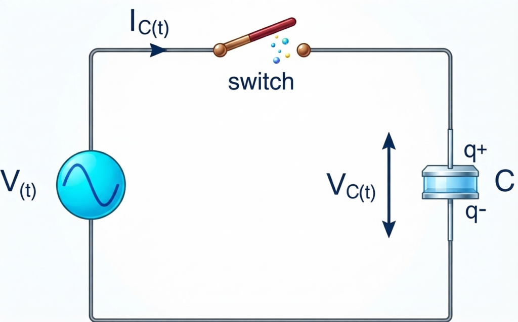
Assume that the non-polarised capacitor is initially fully discharged. When the switch is closed at , current begins to flow into the capacitor because there is initially no stored charge on its plates.
The sinusoidal AC supply voltage continuously rises from zero to a maximum positive value and then falls back to zero. It subsequently changes polarity, reaches a negative maximum, and returns to zero. Therefore, the applied AC voltage is continuously changing in magnitude and direction.
As the voltage initially rises, its rate of change is greatest, so the capacitor current also reaches its maximum value. When the supply voltage reaches its positive peak at 90°, its rate of change momentarily becomes zero. Consequently, the capacitor current falls to zero while the voltage across the capacitor reaches its maximum value .
After this point, the sinusoidal voltage begins to decrease toward zero at 180°. Although the voltage remains positive, the capacitor starts releasing its stored charge, causing the current to flow in the opposite direction.
At 180°, the supply voltage crosses the zero reference point and its rate of change is maximum in the negative direction. The capacitor current therefore reaches its maximum negative value, while the voltage across the capacitor becomes zero.
Thus, in the first half-cycle from 0° to 180°, the current reaches its maximum value one-quarter of a cycle before the voltage reaches its maximum. In a purely capacitive circuit, the current leads the voltage by 90°, or the voltage lags the current by 90°.
The capacitor therefore continues to charge, discharge, and recharge with reversed polarity in step with the AC supply frequency.
Sinusoidal Waveforms for AC Capacitance
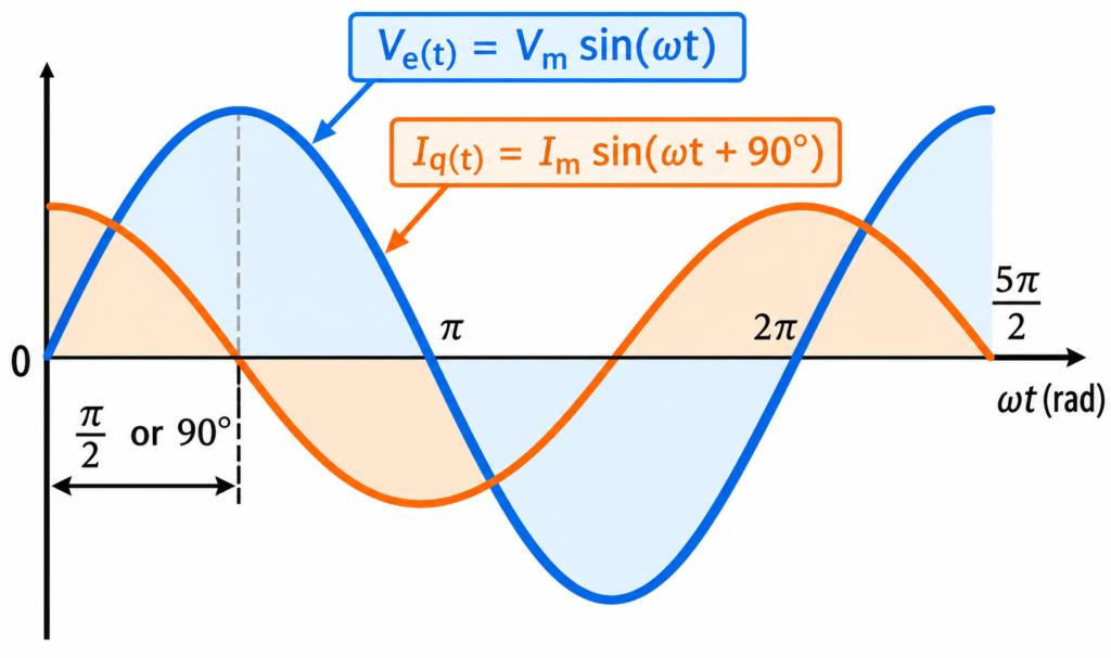
During the second half-cycle, from 180° to 360°, the supply voltage reverses polarity and moves toward its negative peak at 270°. At this point, the voltage reaches its maximum negative value and its rate of change becomes zero, causing the capacitor current to fall to zero.
The capacitor is now fully charged in the opposite direction, with the potential difference across its plates at its maximum negative value. As the negative supply voltage then moves back toward the zero reference at 360°, the capacitor begins to discharge and release its stored charge.
When the supply voltage reaches zero at 360°, the charging and discharging process starts again with the next cycle.
From the voltage and current waveforms, it can be seen that the capacitor current continuously leads the voltage by one-quarter of a cycle, or 90°. This phase difference occurs because the capacitor is continuously charging and discharging in response to the changing AC voltage.
The voltage-current phase relationship in a capacitive circuit is opposite to that of an AC inductive circuit. In a purely capacitive circuit, the voltage lags the current by 90°. Alternatively, when voltage is taken as the reference, the current leads the voltage by 90°, as represented by the corresponding phasor diagram.
Phasor Diagram for AC Capacitance
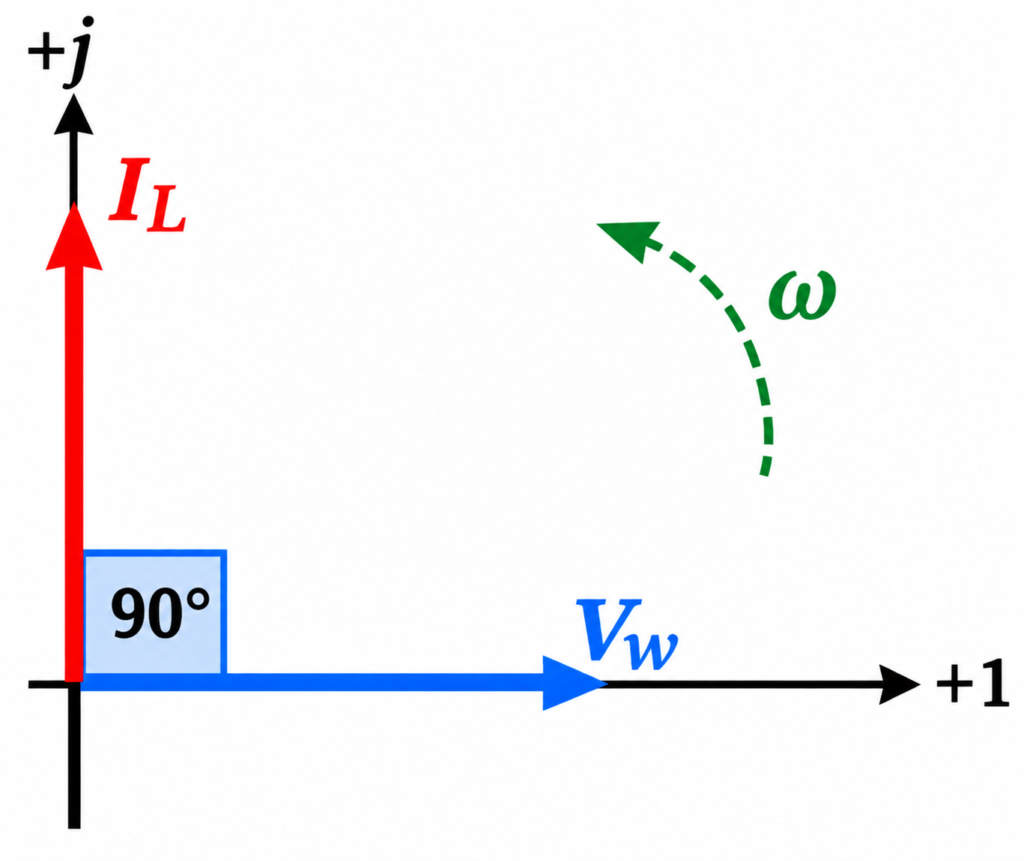
In a pure capacitor, the capacitor voltage lags the capacitor current by 90°, or, equivalently, the current leads the voltage by 90°.
There are several simple methods to remember the phase relationship between voltage and current in a pure AC capacitance circuit. One of the easiest is the mnemonic “ICE.”
The term ICE represents I for current, C for capacitance, and E for electromotive force (voltage). It indicates that current comes before voltage in a capacitor. Therefore, I-C-E = current leads voltage in an AC capacitance circuit.
This relationship remains valid for a pure capacitive circuit regardless of the initial phase angle of the applied voltage.
The Capacitive Reactance of a Capacitor
We know that a capacitor opposes changes in voltage, with electrons flowing onto or away from its plates according to the rate at which the voltage across the capacitor changes.
Unlike a resistor, whose opposition to current flow is called resistance, a capacitor opposes current through a quantity known as reactance.
Reactance, like resistance, is measured in ohms (Ω) and is represented by the symbol X to distinguish it from resistance . For a capacitor, this opposition is specifically called capacitive reactance, represented by and measured in ohms.
Because a capacitor charges and discharges according to the rate of voltage change, a faster-changing voltage allows more current to flow. Conversely, when the voltage changes more slowly, the current through the capacitor decreases.
Therefore, the capacitive reactance of an AC capacitor is inversely proportional to the frequency of the applied AC supply, as shown below.
Capacitive Reactance Formula
Where represents the capacitive reactance in ohms (Ω), is the AC supply frequency in hertz (Hz), and is the capacitance in farads (F).
For an AC capacitance circuit, capacitive reactance can also be expressed using angular frequency. The angular frequency is represented by and is related to frequency by:
This relationship allows the capacitive reactance to be expressed in terms of angular frequency as well.
Capacitive Reactance in Radians
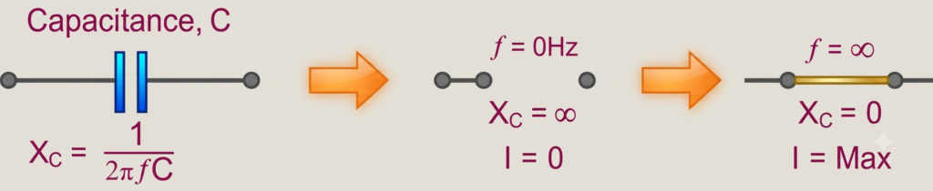
From the capacitive reactance relationship, we can see that , and therefore the impedance offered by a capacitor in an AC circuit, decreases toward zero as frequency increases. At very high frequencies, the capacitor approaches the behaviour of a short circuit.
Conversely, as the frequency approaches zero, or DC, the capacitive reactance increases toward infinity. The capacitor therefore behaves like an open circuit, which explains why a capacitor blocks steady DC current.
The relationship between capacitive reactance and frequency is opposite to that of inductive reactance . Capacitive reactance is therefore inversely proportional to frequency: it has a high value at low frequencies and decreases as the frequency increases, as shown below.
Capacitive Reactance against Frequency
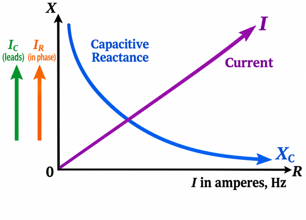
The capacitive reactance of a capacitor decreases as the frequency of the voltage applied across its plates increases.
Therefore, capacitive reactance is inversely proportional to frequency.
Although capacitive reactance opposes the flow of current, the capacitor’s capacitance and its ability to store electric charge remain unchanged.
As frequency increases, the capacitor can accommodate changes in charge more rapidly during each half-cycle. At the same time, the current through the capacitor increases because the voltage across its plates changes at a higher rate.
The effect of very low and very high frequencies on the reactance of a pure AC capacitance can be summarized as follows:
In an AC circuit containing pure capacitance, the current (electron flow) through the capacitor can be expressed as:
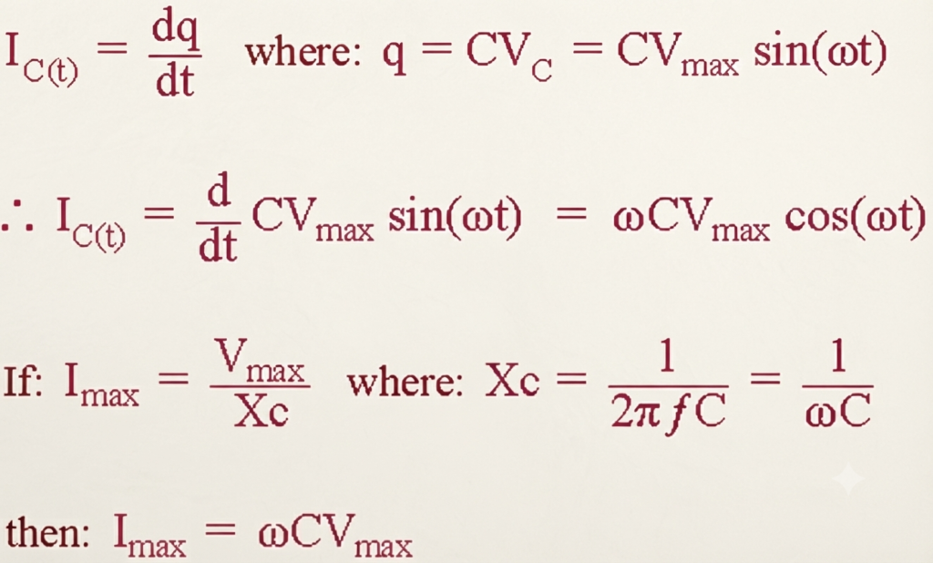
Therefore, the RMS current flowing through an AC capacitance can be expressed as:

Here, represents the magnitude of the capacitor current, while represents the phase angle between the voltage and current. In a purely capacitive circuit, leads by 90°, or equivalently, lags by 90°.
Capacitors in the Phasor Domain
In the phasor domain, the voltage across the plates of an AC capacitor can be expressed as:
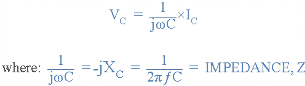
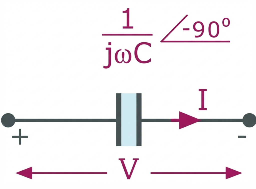
In Polar Form, this can be represented as , where:

Sinusoidal Voltage Across a Series RC Circuit
As discussed earlier, the current in a pure AC capacitance leads the voltage by 90°. However, a truly pure capacitance does not exist in practical circuits because every capacitor has some internal resistance between its plates, which results in a small leakage current.
We can therefore model a practical capacitor as a capacitance, , connected in series with a resistance, . This combination can be considered an “impure capacitor.”
When a capacitor has internal resistance, its total impedance can be represented by a resistance in series with a capacitance. In an AC circuit containing both resistance and capacitance , the voltage phasor across the combination is the phasor sum of the individual voltages and .
The current still leads the applied voltage, but by an angle smaller than 90°, depending on the values of and . The resulting phase difference is represented by the Greek symbol .
Consider the series RC circuit below, in which an ohmic resistance is connected in series with a pure capacitance .
Series Resistance-Capacitance Circuit
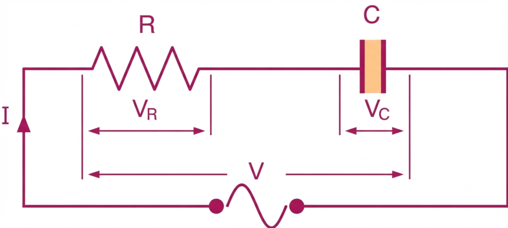
In the RC series circuit above, the same current flows through both the resistance and capacitance, while the total voltage consists of the two component voltages, and .
The resultant voltage can be determined mathematically. However, because the voltage vectors and are 90° out of phase, they must be combined vectorially using a Phasor Diagrm.
To construct a phasor diagram for an AC capacitance circuit, we first need a common reference quantity. In a series AC circuit, the current is common to all components and can therefore be used as the reference. The same current flows through the resistance and the capacitance. The individual phasor diagrams for a pure resistance and a pure capacitance are shown below:
Phasor Diagrams for the Two Pure Components
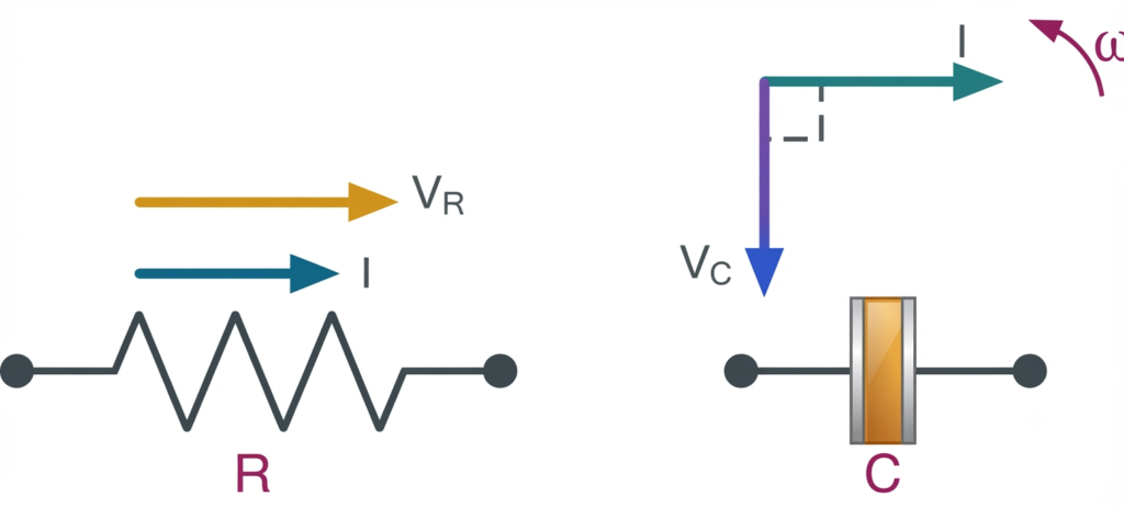
In a pure AC resistance, the voltage and current vectors are in phase with each other. Therefore, the voltage vector is drawn directly over the current vector and to the same scale.
We also know from the ICE relationship that current leads voltage in a pure AC capacitance circuit. Hence, the voltage vector is drawn 90° behind (lagging) the current vector and to the same scale as , as shown above.
Vector Diagram of the Resultant Voltage
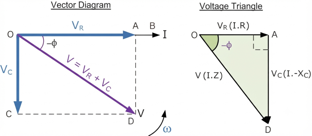
In the vector diagram above, line OB represents the horizontal current reference, while line OA represents the voltage across the resistive component, which remains in phase with the current.
Line OC represents the capacitive voltage, which is 90° behind the current. This again shows that the current leads the purely capacitive voltage by 90°. Line OD represents the resulting supply voltage.
Because the current leads the voltage across a pure capacitance by 90°, the phasor diagram formed by the individual voltage drops and produces the right-angled voltage triangle OAD, as shown above.
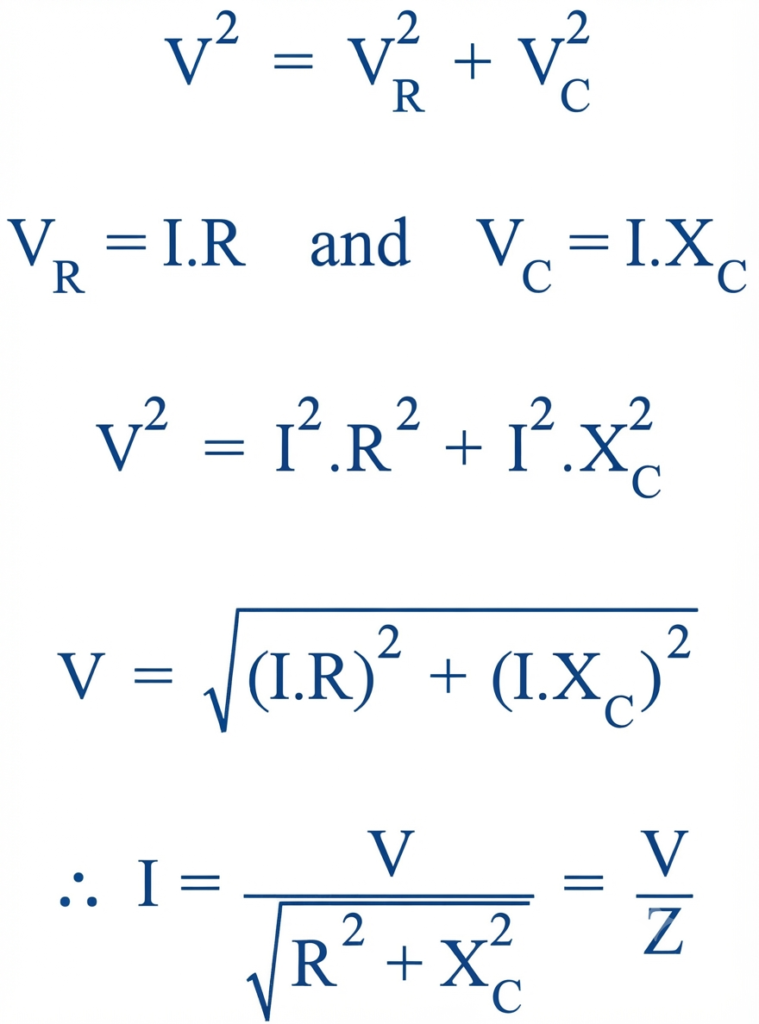
Therefore, Pythagoras’ theorem can be applied to mathematically determine the resultant voltage across the series resistor-capacitor (RC) circuit.
Using Pythagoras’ Theorem
Since and , the applied voltage is the vector sum of the resistive and capacitive voltage drops. Therefore, the resultant voltage can be determined using the relationship below.
The Impedance of an AC Capacitance
Impedance Z, measured in ohms (Ω), represents the total opposition to current flow in an AC circuit containing both resistance (the real component) and reactance (the imaginary component). A purely resistive AC circuit has a phase angle of 0°, whereas a purely capacitive circuit has a phase angle of −90°.
When a resistor and capacitor are connected in the same circuit, the overall impedance has a phase angle between 0° and −90°, depending on the values of the resistance and capacitance. The impedance of the simple RC circuit shown above can therefore be determined using an impedance triangle.
The RC Impedance Triangle
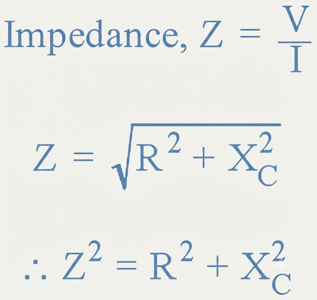
The impedance can therefore be expressed as:
where is the impedance, is the resistance, and is the capacitive reactance. The imaginary component represents the 90° phase shift associated with reactance.
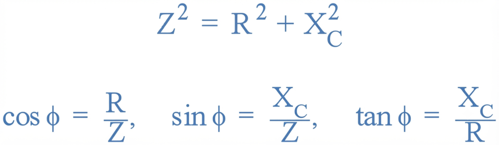
Using Pythagoras’ theorem, the negative phase angle between the voltage and current can then be calculated as:
RC Phase Angle in an AC Circuit
AC Capacitance Worked Example No1
A single-phase sinusoidal AC supply voltage defined as: V(t) = 230 sin(314t – 30°) is connected to a pure AC capacitance of 100 μF. Determine the value of the current flowing into the capacitor and draw the resulting phasor diagram.
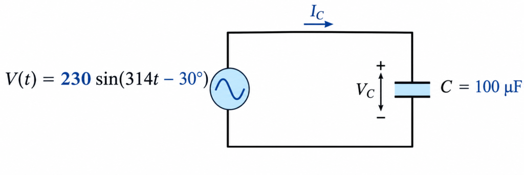
The peak voltage across the capacitor will be the same as the supply voltage. Converting this time-domain value into polar form gives:
The angular frequency is:
For a capacitive circuit, the capacitive reactance is:
Since a capacitor has a phase angle of −90°, its impedance is:
The maximum instantaneous current flowing into the capacitor can be found using Ohm’s law:
For a pure capacitance circuit, the current leads the voltage by 90°. Therefore, the current phasor is:
Thus, the instantaneous current is:
The resulting phasor diagram should show the current vector leading the capacitor voltage vector by 90°.
AC Capacitance Worked Example No2
A capacitor has an internal resistance of 15 Ω and a capacitance of 80 μF. It is connected to an AC supply with the instantaneous voltage given by:
Calculate the peak instantaneous current flowing through the capacitor. Also, construct a voltage triangle showing the individual voltage drops across the internal resistance and the capacitor.
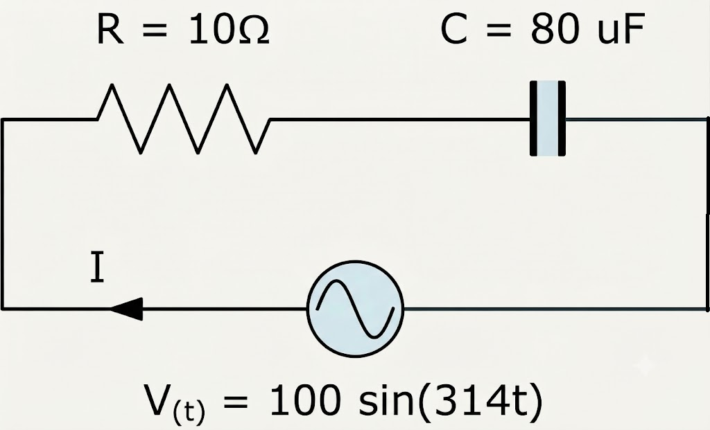
The applied instantaneous voltage is
Therefore, the peak supply voltage is , and the angular frequency is
The capacitive reactance is calculated as:
The capacitive reactance and circuit impedance are calculated as:
The magnitude of the circuit impedance is:
Then the peak current flowing through the capacitor and circuit is:
Phase Angle between the Current and Voltage
The phase angle between the current and voltage is calculated from the impedance triangle:
The negative angle indicates that the circuit is capacitive, so the current leads the supply voltage by approximately 65.7°.
Then the individual peak voltage drops around the circuit are calculated as follows.
Voltage across the internal resistance
Voltage across the capacitor
The small difference caused by rounding can be avoided by using the unrounded current, giving approximately:
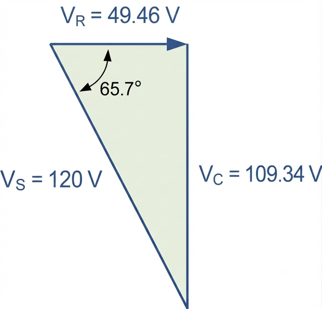
These voltage drops form a right-angle voltage triangle because is in phase with the current, while is 90° behind the current.
RC Voltage Triangle
The resultant supply voltage is:
The voltage triangle can therefore be represented as:
Conclusion
In a pure AC capacitance circuit, the voltage and current are 90° out of phase, with the current leading the voltage by 90°. The simple ICE mnemonic helps us remember this relationship: I (current) leads C (capacitance) E (voltage).
The impedance Z represents the total opposition to AC current, while capacitive reactance represents the reactive opposition provided by the capacitor. Capacitive reactance depends on frequency and capacitance and is given by:
The phase relationship differs among the three basic passive components. A pure resistance has a phase angle of 0°, while pure inductance causes the current to lag the voltage by 90°, corresponding to a phase angle of +90°. In pure capacitance, the current leads the voltage by 90°, giving a phase angle of −90°.
Understanding these voltage-current relationships provides the foundation for analysing circuits containing combinations of resistance, inductance, and capacitance.
Read Next:
- Resistors in Series: Definition, Formula, Rules, Calculation, and Examples
- Capacitors in Series and Series Capacitor Circuits – Complete Guide
- Resistors in Parallel – Parallel Connected Resistors Explained
- Voltage Divider: Rule, Equations, Formulas, and Practical Applications
- Introduction to Capacitor, Capacitance and Charge
- MOS Capacitor and MOS Capacitance C V Curve
- Inductor: Definition, Formula, Working Principle, Types & Applications