Discover the key difference between half-wave and full-wave rectifier. Understand their working principles, advantages, disadvantages, and applications in electronics. Learn how these rectifiers convert AC to DC, enhancing efficiency and reducing ripple in power supplies and electronic circuits.
Rectification is a crucial process in electronics, converting alternating current (AC) to direct current (DC). Rectifiers are the devices that perform this conversion, and they come in two main types: half-wave and full-wave rectifiers. Understanding the differences between these two types of rectifiers is essential for designing and working with electronic circuits. This article explores the key distinctions between half-wave and full-wave rectifiers, their working principles, advantages, disadvantages, and applications.
What is a Rectifier?
A rectifier is an electronic device that converts AC to DC. AC voltage alternates between positive and negative values, whereas DC voltage maintains a constant polarity. Rectifiers are fundamental components in power supplies, providing the necessary DC voltage for electronic devices and circuits.
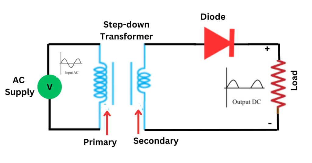
Half-Wave Rectifier
Working Principle
A half-wave rectifier uses a single diode to convert AC to DC. It only allows one-half of the AC waveform to pass through, blocking the other half. This results in a pulsating DC output that corresponds to the positive (or negative) half-cycles of the input AC signal.
- Positive Half-Cycle: During the positive half-cycle of the AC input, the diode becomes forward-biased and conducts current, allowing the positive half-cycle to pass through to the load resistor.
- Negative Half-Cycle: During the negative half-cycle, the diode becomes reverse-biased and blocks current, preventing the negative half-cycle from reaching the load.
Circuit Diagram
The basic circuit of a half-wave rectifier consists of:
- An AC source
- A single diode
- A load resistor
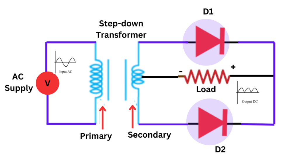
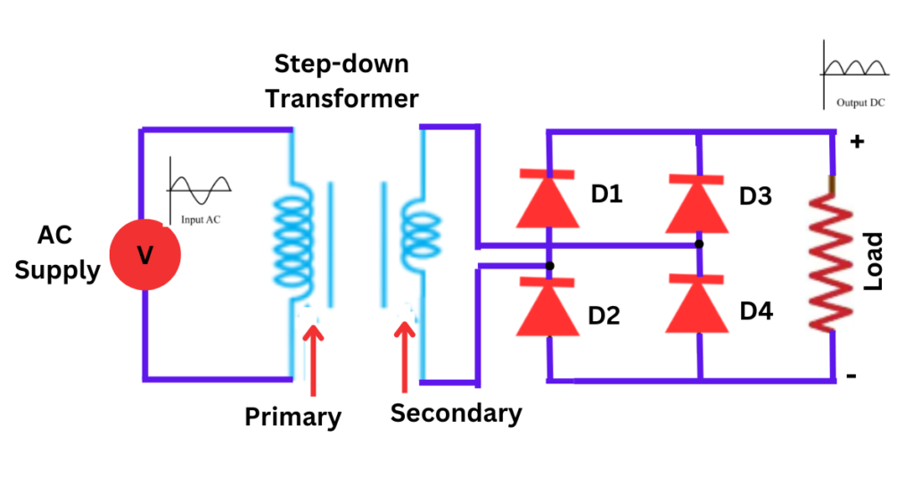
Full-Wave Rectifier
Working Principle
A full-wave rectifier converts the entire AC waveform to DC. It uses two or four diodes, depending on the configuration, to allow both the positive and negative half-cycles of the AC input to pass through, producing a smoother and more efficient DC output.
Types of Full-Wave Rectifiers
- Center-Tapped Full-Wave Rectifier: Uses a center-tapped transformer and two diodes. The center tap serves as the ground, and each diode conducts during alternate half-cycles of the AC input.
- Bridge Full-Wave Rectifier: Uses four diodes arranged in a bridge configuration. This design does not require a center-tapped transformer and is more commonly used.
Circuit Diagrams
Center-Tapped Full-Wave Rectifier:
Bridge Full-Wave Rectifier:
Key Differences Between Half-Wave and Full-Wave Rectifiers
Efficiency
- Half-Wave Rectifier: Lower efficiency as it only utilizes one-half of the AC input.
- Full-Wave Rectifier: Higher efficiency as it utilizes both half-cycles of the AC input.
Ripple Factor
- Half-Wave Rectifier: Higher ripple factor, resulting in more fluctuations in the DC output.
- Full-Wave Rectifier: Lower ripple factor, producing a smoother DC output.
Complexity and Cost
- Half-Wave Rectifier: Simple design with fewer components, making it cheaper.
- Full-Wave Rectifier: More complex with more components, leading to higher cost.
Output Voltage
- Half-Wave Rectifier: The average output voltage is lower due to the use of only half the AC waveform.
- Full-Wave Rectifier: Higher average output voltage as it uses the entire AC waveform.
Applications
- Half-Wave Rectifier: Suitable for low-power, non-critical applications.
- Full-Wave Rectifier: Preferred for high-power, critical applications requiring stable and efficient DC output.
Differences Between Half-Wave and Full-Wave Rectifiers- Tabular Form
| Feature | Half-Wave Rectifier | Full-Wave Rectifier |
|---|---|---|
| Working Principle | Converts only one half of the AC waveform to DC | Converts both halves of the AC waveform to DC |
| Diode Requirement | One diode | Two diodes (center-tapped) or four diodes (bridge) |
| Circuit Complexity | Simple | More complex |
| Transformer Requirement | Not required | Center-tapped transformer (for center-tapped type) |
| Efficiency | Lower (uses only half of the AC signal) | Higher (uses entire AC signal) |
| Ripple Factor | Higher (more ripple) | Lower (less ripple) |
| Output Voltage | Lower average output voltage | Higher average output voltage |
| Peak Inverse Voltage (PIV) | Equal to the peak value of the AC input | Twice the peak value of the AC input (for center-tapped) |
| Cost | Lower (fewer components) | Higher (more components) |
| Applications | Low-power devices, signal demodulation, basic power supplies | Power supplies for electronic devices, battery charging, industrial applications |
| Advantages | Simple design, low cost | Higher efficiency, smoother DC output, greater power delivery |
| Disadvantages | High ripple, low efficiency, limited applications | More complex, higher cost |
This table provides a clear comparison of the key features and differences between half-wave and full-wave rectifiers.
Conclusion
Understanding the difference between half-wave and full-wave rectifiers is crucial for selecting the appropriate rectifier for a given application. While half-wave rectifiers offer simplicity and low cost, they are less efficient and produce more ripple. Full-wave rectifiers, on the other hand, provide higher efficiency and smoother DC output but at the cost of increased complexity and expense. Choosing the right rectifier depends on the specific requirements of the application, including power levels, efficiency needs, and budget constraints.