Discover the complete guide to diode specifications, ratings, and parameters. Learn about diode types, voltage ratings, current limits, thermal resistance, and more to choose the right diode for your application.
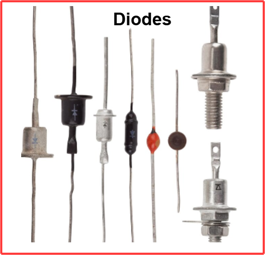
Diodes are essential semiconductor devices used in various electronic circuits. They allow current to flow in one direction while blocking it in the reverse direction. Diodes are widely used in rectifiers, voltage regulators, signal processing, and other applications.
Choosing the right diode for a specific application requires a clear understanding of its specifications, ratings, and parameters. These specifications define the diode’s performance and operating conditions. Selecting an unsuitable diode can lead to inefficiencies, excessive heat, or circuit failure.
Some of the most important diode specifications include forward voltage drop (VF), peak inverse voltage (PIV), reverse breakdown voltage (VBR), maximum forward current, leakage current, junction temperature, and thermal resistance. Each parameter is critical in ensuring that the diode functions efficiently within its limits.
For example, forward voltage drop determines the energy loss in a diode, while peak inverse voltage specifies the highest reverse voltage a diode can withstand before breaking down. Similarly, maximum forward current ensures the diode operates without overheating, and junction capacitance affects its performance in high-frequency circuits.
Additionally, diodes are made from different semiconductor materials like silicon, germanium, and gallium arsenide, each affecting their efficiency and application. The package type of a diode, such as surface-mount or through-hole, also influences its thermal dissipation and ease of installation.
This guide provides a detailed explanation of various diode specifications helping you select the correct component for your application. Understanding these parameters will ensure optimal circuit performance and longevity while preventing component failure due to incorrect selection.
Diode specifications ratings and parameters
The specifications of a diode determine its performance in a circuit. These ratings define the limits within which a diode can operate safely. Understanding these parameters is crucial for designing efficient electronic systems.
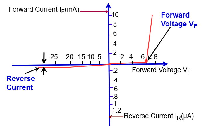
Diodes have several key ratings that must be considered. Forward voltage drop (Vf) is the voltage required for current to flow through the diode in the forward direction. Peak inverse voltage (PIV) refers to the maximum reverse voltage a diode can withstand before breakdown occurs. Reverse breakdown voltage V(BR)R is the point at which a diode begins conducting in reverse, which is useful in Zener diodes.
Another important factor is maximum forward current, which defines the highest current the diode can handle in the forward direction without damage. Leakage current is the small current that flows when the diode is reverse-biased, and it should be minimal for high-performance applications. Junction capacitance impacts the diode’s ability to handle high-frequency signals.
Thermal parameters like junction temperature and junction-to-ambient thermal resistance (θJA) affect the diode’s efficiency and reliability. The package type also influences the diode’s heat dissipation and ease of mounting.
Understanding these specifications ensures the diode operates within safe limits, preventing failures and ensuring long-term circuit stability. By carefully selecting the right diode based on its ratings, engineers can design more efficient and reliable electronic systems.
The following list outlines the key diode characteristics and parameters found in datasheets and specifications.
Semiconductor Material
Diodes are made from different semiconductor materials such as silicon and germanium. Each material has unique electrical properties that impact the diode’s performance and application.
Silicon: Silicon is the most widely used semiconductor material for diodes. Silicon diodes offer high thermal stability, low leakage current, and excellent reliability. They typically have a forward voltage drop of 0.6V to 0.7V, making them suitable for rectification and switching applications. Due to their high breakdown voltage and ability to handle large currents, silicon diodes are commonly used in power electronics and voltage regulation circuits. Additionally, silicon diodes have low sensitivity to temperature variations, ensuring stable operation in various environmental conditions.
Germanium: Germanium diodes have a lower forward voltage drop of 0.2V to 0.3V, making them ideal for applications requiring low-voltage operation, such as radio detection circuits and signal demodulation. However, they have higher leakage currents and lower thermal stability than silicon diodes. Due to their sensitivity to temperature changes, germanium diodes are used in specialized applications where low-voltage operation is critical. While less common in modern electronics, they are still used in vintage radio receivers and certain high-frequency applications.
Other materials are typically used for specialized diodes. For instance, LEDs utilize compound materials to produce various colors.
Diode Type
There are different types of diodes, each designed for specific applications. Rectifier diodes are used in power supplies to convert AC to DC, handling high current and voltage. Zener diodes operate in reverse breakdown mode to regulate voltage, making them useful in voltage regulation circuits.
Forward Voltage Drop Specification (Vf)
Forward voltage drop (Vf) is a critical parameter that determines the voltage required for a diode to conduct current in the forward direction. This value varies depending on the type of diode and the semiconductor material used. The forward voltage drop must be considered when designing circuits to ensure minimal energy loss and efficient performance.
Silicon diodes have a forward voltage drop ranging between 0.6V to 0.7V. These diodes are widely used in rectifier circuits, switching applications, and voltage regulation due to their stability and efficiency. Their higher forward voltage drop makes them suitable for power applications where voltage losses are not a significant concern.
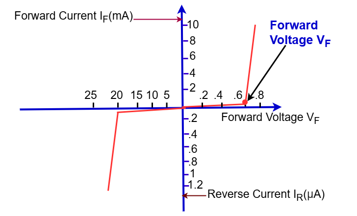
Germanium diodes, on the other hand, have a lower forward voltage drop of 0.2V to 0.3V. This lower voltage requirement makes them ideal for applications requiring minimal power loss, such as radio frequency (RF) circuits and signal detection. However, their higher leakage current and lower thermal stability limit their use in high-power applications.
Schottky diodes have an even lower forward voltage drop, typically between 0.15V to 0.45V. This makes them ideal for high-frequency applications, power efficiency improvements, and fast-switching circuits. Their low voltage drop enhances efficiency, especially in low-voltage power supplies and high-speed switching applications.
Selecting the appropriate diode based on forward voltage drop is crucial in circuit design. Lower voltage drop diodes reduce energy losses, improving the efficiency and performance of electronic devices. However, factors like leakage current, temperature stability, and power handling must also be considered to ensure optimal operation.
Schottky diodes have a low forward voltage drop and fast switching speed, making them ideal for high-frequency and power applications. Light-emitting diodes (LEDs) produce light when current flows through them and are widely used in displays, indicators, and lighting systems.
Other types include photodiodes, which detect light, and tunnel diodes, which exhibit negative resistance and are used in high-frequency applications. Each diode type has unique electrical characteristics suited for different circuit requirements.
Peak Inverse Voltage Specification (PIV)
Peak Inverse Voltage (PIV) is a crucial specification that determines the maximum reverse voltage a diode can withstand without experiencing a breakdown. This is particularly important in rectifier circuits, where the diode must block reverse voltage when alternating current (AC) reverses polarity.
A diode with a high PIV rating is necessary for high-voltage applications, ensuring that the diode does not conduct in reverse and remains intact under high reverse voltage conditions. If the reverse voltage exceeds the diode’s PIV rating, it may break down, leading to circuit failure or damage.
For low-voltage circuits, diodes with a lower PIV rating may be sufficient. However, in power rectifiers, voltage multipliers, and high-voltage applications, selecting a diode with a sufficiently high PIV rating is essential for reliable operation. Common rectifier diodes like the 1N4007 have a PIV rating of 1000V, making them suitable for high-voltage rectification.
In practical circuit design, engineers often select a diode with a PIV rating at least twice the peak AC voltage to ensure safety margins. This approach minimizes the risk of voltage spikes exceeding the diode’s capacity, thus enhancing circuit durability and performance.
Reverse Breakdown Voltage Specification V(BR)R
Reverse Breakdown Voltage V(BR)R is the voltage at which a diode begins conducting heavily in reverse bias. When a diode is subjected to a voltage beyond this limit, it undergoes breakdown, allowing significant current to flow. This can lead to permanent damage in standard diodes.
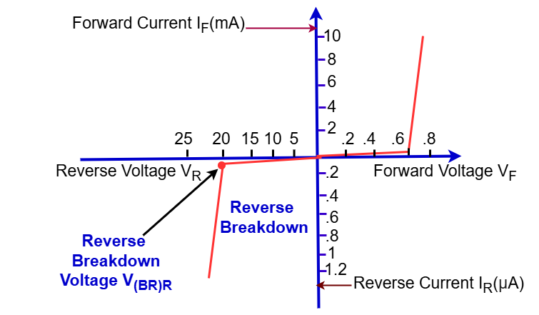
However, Zener diodes are specifically designed to operate in this region. They regulate voltage by allowing controlled reverse breakdown without damage, making them useful in voltage regulation circuits. Standard diodes should not exceed their V(BR)R rating to avoid failure.
For general-purpose diodes, the reverse breakdown voltage typically ranges from 50V to 1000V, depending on the diode type. Selecting a diode with a higher V(BR)R ensures circuit reliability and prevents unintended breakdown.
Maximum Forward Current
Maximum forward current is the highest amount of current a diode can conduct in the forward direction without suffering damage. This specification is crucial because exceeding this limit can cause excessive heat buildup, potentially leading to diode failure.
Diodes designed for power applications typically have high forward current ratings, often ranging from a few amperes to hundreds of amperes. Small-signal diodes, on the other hand, have much lower ratings, typically in the milliampere range.
When selecting a diode, it is essential to consider the circuit’s operating current and ensure that the chosen diode can handle it safely. Proper heat dissipation techniques, such as using heat sinks, can also help manage higher current loads.
Exceeding the maximum forward current limit can lead to thermal runaway, degradation of diode performance, and eventual failure. Always verify this specification to ensure reliable and efficient circuit operation.
Junction Operating Temperature
Diodes have a specified temperature range within which they can function correctly. This range is typically from -55°C to 150°C, but it varies depending on the diode type and material.
Operating a diode beyond its rated junction temperature can lead to performance degradation, increased leakage current, and even permanent failure. The higher the temperature, the greater the risk of thermal runaway, where excessive heat leads to further current increase, causing breakdown.
Silicon diodes generally have higher thermal stability compared to germanium diodes. While silicon diodes can operate up to 150°C, germanium diodes usually have a lower limit of around 80°C to 100°C. This makes silicon diodes more suitable for high-power and high-temperature applications.
Proper thermal management techniques, such as heat sinks, adequate ventilation, and PCB design, help maintain diode temperature within safe operating limits. Junction-to-ambient thermal resistance (θJA) is an important parameter that affects temperature control.
When designing a circuit, it is crucial to consider ambient temperature conditions and ensure that the selected diode can handle variations in temperature without failure. Choosing a diode with a higher junction temperature rating can improve long-term reliability and efficiency.
Junction-to-Ambient Thermal Resistance (θJA)
Junction-to-ambient thermal resistance (θJA) is a critical parameter that defines how effectively a diode can dissipate heat from its junction to the surrounding environment. It is measured in °C/W and directly affects the diode’s reliability and performance, especially in high-power applications.
The junction-to-ambient thermal resistance is actually the sum of a series of individual resistances within the diode structure: junction-to-case thermal resistance, case-to-surface thermal resistance, and surface-to-ambient thermal resistance. This relationship is given by the formula: θJA = θJC + θCS + θSA.
Where:
- θJA= Junction-to-ambient thermal resistance
- θJC= Junction-to-case thermal resistance
- θCS= Case-to-surface thermal resistance
- θSA= Surface-to-ambient thermal resistance
This overall specification is key in determining the actual junction operating temperature. Monitoring this parameter is crucial in circuits where diodes carry significant current, leading to power dissipation.
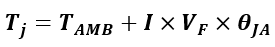
The junction temperature can be calculated using the formula:
Where:
- TJ= Junction temperature
- TAMB= Ambient temperature
- I= Forward current
- VF= Forward voltage drop
- θJA= Junction-to-ambient thermal resistance
A lower θJA value means better heat dissipation, making the diode more suitable for high-power applications where efficient thermal management is crucial.
Leakage Current Specification
Leakage current is the small amount of current that flows through a diode when it is reverse-biased. Ideally, a diode should block current flow in the reverse direction, but due to the nature of semiconductor materials, a small leakage current is always present. This leakage current is also referred to as reverse saturation current or reverse leakage current and is typically measured in nanoamperes (nA) or microamperes (µA).
Silicon diodes exhibit significantly lower leakage currents compared to germanium diodes. This is because silicon has a wider bandgap (1.12 eV) than germanium (0.66 eV), making it less susceptible to thermally generated carriers. As a result, silicon diodes are preferred in applications where minimal leakage is required, such as precision rectifiers and low-noise circuits.
Leakage current increases with temperature, as higher temperatures generate more charge carriers within the semiconductor material. Therefore, diodes operating at elevated temperatures may experience higher leakage, affecting circuit performance. Manufacturers specify the maximum leakage current at a given reverse voltage and temperature, typically denoted as in datasheets.
Junction Capacitance
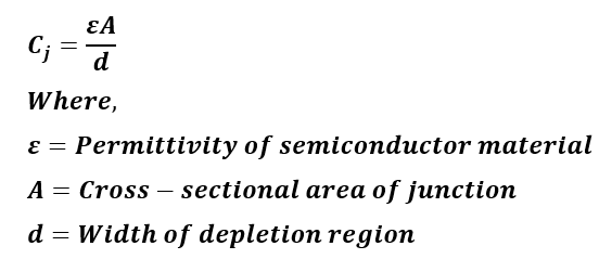
Junction capacitance is an important parameter that affects a diode’s high-frequency performance. It arises due to the depletion region acting as a capacitor when the diode is reverse-biased. This capacitance is influenced by factors such as doping concentration, applied reverse voltage, and the physical structure of the diode.
Junction capacitance is particularly crucial in high-frequency applications, such as RF circuits and fast-switching power electronics. Diodes with high capacitance can cause unwanted signal distortion and slow switching speeds. To address these issues, low-capacitance diodes, such as Schottky diodes and fast-recovery diodes, are preferred.
The junction capacitance CJ is given by the equation:
To minimize leakage current in sensitive applications, Schottky diodes or special low-leakage diodes are used. Additionally, proper heat dissipation and maintaining operation within specified temperature limits help control leakage current levels effectively.
Reverse Recovery Time (trr)
Reverse recovery time (trr) is the time a diode takes to stop conducting when the voltage polarity reverses. When a diode transitions from forward bias to reverse bias, residual charge carriers must be removed before it can fully block the reverse current. This parameter is critical in high-speed switching applications like rectifiers, power supplies, and signal processing circuits. A longer trr can cause higher power losses and inefficiencies in fast-switching circuits.
Fast-recovery diodes and Schottky diodes are designed with low trr values, typically in the nanosecond range, making them ideal for high-frequency applications. A shorter reverse recovery time reduces switching losses and enhances efficiency, which is especially important in RF circuits, pulse rectification systems, and switching power supplies. Choosing a diode with an appropriate trr ensures optimal performance in high-speed electronic designs.
Power Dissipation(PD)
Power dissipation (Pd) in a diode refers to the amount of power converted into heat as the diode conducts current. This power loss is calculated using the formula PD = VF× IF, where VF is the forward voltage drop, and IF is the forward current. Since diodes generate heat during operation, excessive power dissipation can lead to overheating and reduced efficiency, potentially damaging the component if it exceeds its rated limits.
The power dissipation capacity of a diode depends on factors like its package type, thermal resistance, and surrounding operating conditions. Diodes in high-power applications, such as rectifiers and switching circuits, must be chosen based on their ability to handle heat efficiently. Semiconductor manufacturers specify maximum Pd ratings, ensuring safe operation within a given temperature range.
To prevent overheating, proper thermal management techniques must be used. Heat sinks, PCB layout optimization, and forced air cooling can improve heat dissipation. Surface-mount diodes often rely on PCB copper traces for thermal conduction, while power diodes may require additional heat dissipation mechanisms. Ensuring adequate heat dissipation enhances the diode’s reliability and extends its operational lifespan.
Surge Current Rating (Ifsm)
The surge current rating (Ifsm) represents the maximum peak current a diode can endure for a brief moment without sustaining damage. Unlike continuous forward current, which a diode can handle steadily, Ifsm accounts for sudden, high-current pulses that may arise in circuits. This specification is especially crucial in power rectifiers, where inrush currents occur when switching on devices such as transformers, motors, or power supplies.
Typically, the Ifsm rating is much higher than the diode’s continuous current rating, often measured over a duration of 8.3 milliseconds (one half-cycle of AC mains power). Exceeding this rating can cause thermal or mechanical stress, leading to failure.
To protect diodes from excessive surge currents, circuit designers often use inrush current limiters, resistors, or thermistors. Choosing a diode with an adequate Ifsm ensures reliability in applications where current surges are expected.
Package Type
Diodes come in various package types, including through-hole (DO-41, DO-201) and surface-mount (SOD-123, SOT-23). The package determines mounting and thermal characteristics.
Diodes can be mounted in a variety of packages according to their applications, and in some circumstances, especially RF design applications, the package is a key element in defining the overall RF diode characteristics.
For power applications where heat dissipation is important, the package can define many of the overall diode parameters. High-power diodes may require packages that can be bolted to heatsinks, whereas small signal diodes where heat dissipation is not an issue may be available in leaded formats or as surface mount devices.
High-power diodes may also be available as bridge rectifiers, containing four diodes in a bridge configuration suitable for full-wave rectification applications.
Surface mount diodes (SMD diodes) are used in vast quantities because most electronics manufacturing and PCB assembly are undertaken using automated techniques, and surface mount technology lends itself to this.
Diode bridge rectifiers are widely used in power supply applications and other power circuit designs. These bridge rectifiers typically come with clearly marked terminals to indicate proper connections.
Additionally, diodes come in both leaded and surface-mount technology packages, depending on the type. Most RF and low-power diodes are available in surface-mount packages, making them ideal for large-scale manufacturing.
Diode Coding and Marking Schemes
Diodes are marked with codes indicating their specifications. Standard marking includes part numbers, voltage ratings, and current ratings. The JEDEC and Pro-Electron schemes are widely used for diode identification.
JEDEC codes typically use alphanumeric designations, while the Pro-Electron scheme often follows a structured format to indicate diode type and characteristics.
For example, the code “13s” indicates a BAS125 surface mount diode in an SOT23 or SOT323 package. Data sheets provide comprehensive information on these codes, helping engineers select the appropriate diode for their application.
Manufacturers may also use proprietary marking systems, but standard codes ensure consistency and easy identification of diode specifications across different brands and models.
Example of typical diode specifications
Despite the wide variety of diodes with numerous specifications, it can be helpful to understand their parameters and how they are presented in a format similar to that found in datasheets.
Below is a specifications table for the 1N4007 diode:
| Characteristic | Typical Value | Unit | Details |
| Max DC Blocking Voltage, Vr | 1000 | V | |
| Max Forward Continuous Current, Ifm | 1 | A | |
| Reverse Breakdown Voltage, V(BR)R | 1000 | V | @ reverse current of 10µA |
| Reverse Leakage Current, IR | 5 | µA | At VR = 25°C |
| Forward Voltage Drop, VF | 0.7 | V | At IF = 1.0 A |
| Junction Capacitance, Cj | 15 | pF | VR = 0V, f = 1MHz |
| Reverse Recovery Time, trr | 2 | µs |
These specs help in selecting the 1N4007 diode for appropriate applications, ensuring reliable performance under defined operating conditions.
The 1N4007 is a commonly used general-purpose diode, and its specifications indicate the typical values it provides. Matching its performance to the circuit design is essential. Other semiconductor diodes have different parameters and may be suitable for various applications and circuit designs. This is just an example specification, and other diodes may offer significantly different performance levels.
Conclusion
Understanding diode specifications is essential for selecting the right diode for your circuit. By considering key parameters like VF, PIV, maximum current, and thermal resistance, you can ensure optimal performance and reliability in your applications.-
Read Next: