Mutual inductance is the phenomenon in which a changing current in one coil produces a varying magnetic field that links with a nearby coil, inducing a voltage in the second coil.
What Is Mutual Inductance?
Mutual inductance is the property of two magnetically coupled coils in which a change in current through one coil produces a changing magnetic field that links with the second coil and induces a voltage in it. The coils may be electrically isolated but interact through their shared magnetic field. Mutual inductance depends on factors such as the number of turns, coil arrangement, distance between the coils, and the magnetic permeability of the core.
Mutual Interaction of Coils
When the current flowing through a coil changes, it produces a changing magnetic field that induces an electromotive force (EMF) in the same coil. This phenomenon is known as self-induction, represented by the symbol .
When the changing magnetic field produced by one coil links with a nearby coil and induces an EMF in it, the phenomenon is called mutual induction. The property that describes the magnetic interaction between two coils is known as mutual inductance, represented by the symbol .
Mutual induction is the fundamental operating principle of transformers and plays an important role in various electrical machines and electromagnetic devices. In simple terms, a changing current in one coil induces a voltage in another magnetically coupled coil through their shared magnetic flux.
Disadvantages of Mutual Inductance
Although mutual inductance is essential in devices such as transformers, unwanted magnetic coupling between nearby coils can cause problems. For example, stray magnetic fields from one coil may induce unwanted voltages in adjacent circuits, leading to electromagnetic interference (EMI). This interference can introduce noise, distort signals, and affect the performance of sensitive electronic equipment.
To reduce unwanted coupling, engineers may increase the distance between components, adjust their orientation, use magnetic shielding, or apply suitable grounding and cable-routing practices where appropriate.
Effect of Distance on Magnetic Coupling
The mutual inductance between two coils depends on how effectively the magnetic flux produced by one coil links with the turns of the other coil. Their relative position, orientation, separation, and core arrangement all influence this magnetic coupling.
When two coils are placed close together and oriented to maximize flux linkage, a larger portion of the magnetic flux from the first coil may pass through the second coil. This generally produces stronger magnetic coupling and higher mutual inductance.
As the distance between the coils increases, more of the magnetic field spreads into the surrounding space instead of linking with the second coil. Consequently, the mutual inductance usually decreases. Changing the angle between the coils can also reduce flux linkage and weaken the coupling.
When the coils are sufficiently far apart, their mutual inductance may become negligible for practical purposes. Therefore, the distance and relative orientation of coils are important factors in determining mutual inductance.
Unit of Mutual Inductance
The SI unit of mutual inductance is the henry (H). One henry is the mutual inductance when a current changing at a rate of 1 A/s in the primary coil induces an emf of 1 V in the secondary coil.
Mutual Inductance Between Coils
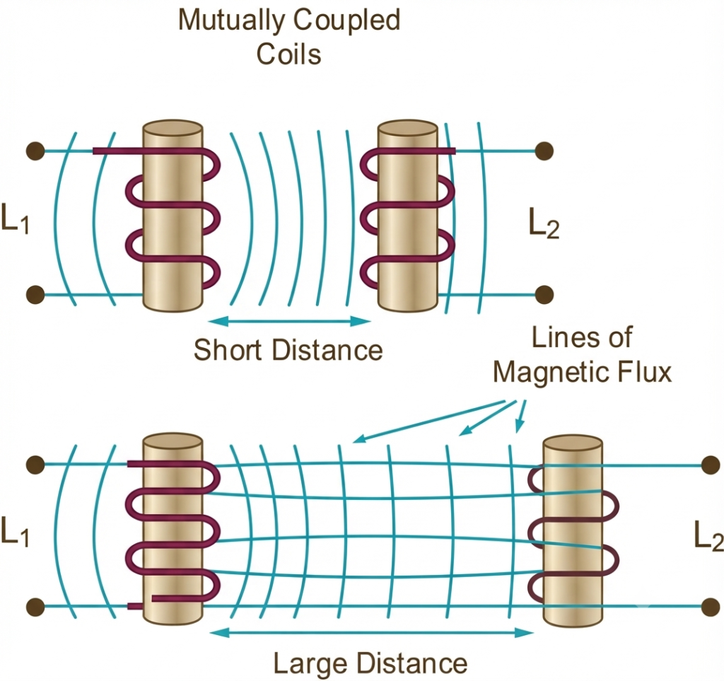
Mutual inductance between two coils can be increased by placing them on a common soft iron core or by increasing the number of turns in either coil. This arrangement improves magnetic flux linkage between the coils and is commonly used in devices such as voltage transformers.
When two coils are wound closely together on the same soft iron core, most of the magnetic flux produced by one coil can link with the other. In an ideal case, perfect magnetic coupling exists, with the coupling coefficient \(k=1\). In practical circuits, some flux leakage usually occurs, so the coupling coefficient is generally less than one.
For two tightly coupled coils, the mutual inductance depends on their number of turns, the core’s geometry and magnetic permeability, and the degree of magnetic coupling. The relationship can be expressed as:
Mutual Inductance Formula Using Permeability and Turns
Where:
- µo is the permeability of free space (4π x 10–7)
- µr is the relative permeability of the soft iron core
- N is in the number of coil turns
- A is in the cross-sectional area in m2
- ℓ is the coils length in meters
Formula Derivation of Mutual Inductance Between Two Coaxial Coils
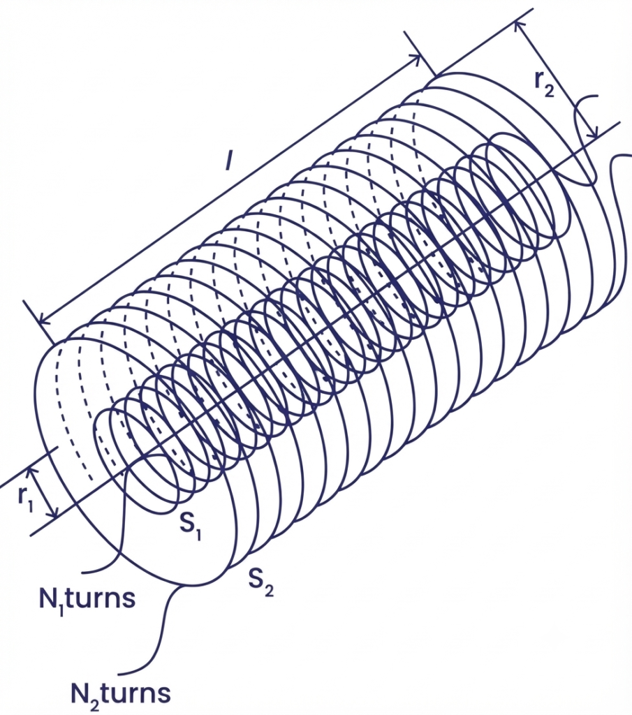
Let and be two long coaxial coils of length , each having a cross-sectional area. Let and represent the number of turns in coils and , respectively.
When an electric current flows through the primary coil , it produces a magnetic field. This magnetic field generates magnetic flux that links with the secondary coil .
The mutual inductance depends on the magnetic flux linked with the secondary coil due to the current flowing through the primary coil.
Step 1: Magnetic Flux Linked With Coil S2
The magnetic flux linked with a coil is given by:
where:
- is the number of turns in the secondary coil.
- is the magnetic flux through each turn of due to current in .
Since magnetic flux is given by , we obtain:
Step 2: Magnetic Field Produced by Coil S1
The magnetic field inside a long solenoid is given by:
The number of turns per unit length is:
Substituting this value into the magnetic field equation:
where is the permeability of free space.
Step 3: Substitute the Magnetic Field Into the Flux Equation
Substituting Equation (3) into Equation (2):
we get:
Simplifying:
Step 4: Calculate Mutual Inductance
Mutual inductance is defined as the magnetic flux linkage of the secondary coil per unit current flowing through the primary coil:
Using Equation (4):
Therefore, the mutual inductance between two long coaxial coils is:
This formula assumes that both coils share the same cross-sectional area, the magnetic field is approximately uniform inside the coils, and leakage flux and end effects are negligible.
Mutual Induction Between Two Adjacent Coils
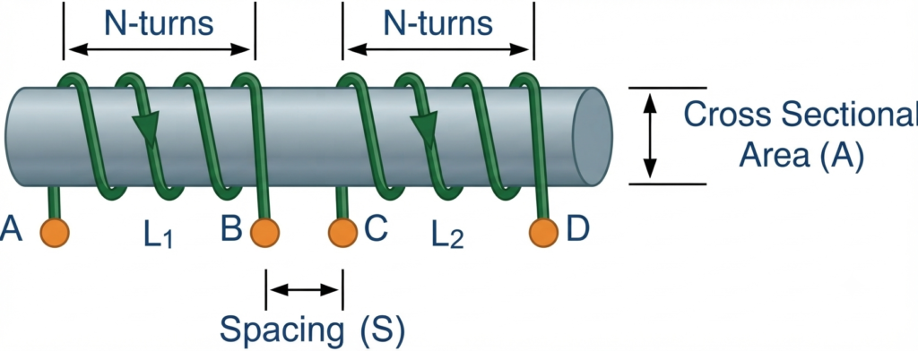
When current flows through the primary coil, , it produces a magnetic field around the coil. Since both coils are wound on a common core, a portion of the magnetic flux generated by links with the turns of the second coil, . If the current in the primary coil changes, the changing magnetic flux induces a voltage in the second coil. This phenomenon is known as mutual induction.
The mutual inductance between the two coils depends on their number of turns, core properties, relative positions, and the amount of magnetic flux linking both coils. The number of turns in the primary coil is represented by , while the number of turns in the secondary coil is represented by .
The mutual inductance of coil 2 with respect to coil 1, denoted by , can be expressed as:
Mutual Inductance Between Two Coils
and,
By combining the mutual inductance equations for both coils, the mutual inductance under ideal magnetic coupling can be expressed in terms of their self-inductances. For perfect coupling, where all the magnetic flux produced by either coil links with the other coil, the relationship is:
Mutual Inductance Using the Individual Inductances of the Coils
For two perfectly coupled coils, the mutual inductance is determined by the geometric mean of their individual self-inductances:
Mutual Inductance Between Coils
Taking the square root gives the final expression:
The equation assumes perfect magnetic coupling between the two coils, meaning that all the magnetic flux produced by either coil links with the other coil. Under this ideal condition, the coefficient of coupling is .
In practical applications, some magnetic flux fails to link both coils and instead spreads into the surrounding space. This is known as flux leakage, which reduces the coupling between the coils. However, winding the coils closely together on a common magnetic core can minimize leakage and improve magnetic coupling.
The coefficient of coupling, represented by the lowercase letter , indicates the fraction of magnetic coupling between two coils. Its value ranges from 0 to 1, where represents no mutual coupling and represents perfect coupling.
Coupling Coefficient
The degree of magnetic coupling between two coils is represented by the coefficient of coupling, denoted by . It is expressed as a dimensionless value ranging from 0 to 1. A value of indicates no mutual magnetic coupling, while represents ideal coupling, in which all the magnetic flux produced by one coil links with the other.
Depending on the coupling coefficient, coils may be described as tightly or loosely coupled. A higher value of indicates stronger magnetic coupling, whereas a lower value indicates weaker coupling. The terms tightly coupled and loosely coupled are descriptive rather than universal classifications, so a value such as is not a strict boundary.
By including the coupling coefficient in the mutual inductance equation, the relationship becomes:
Coupling Factor Between Coils
When , the coils have ideal magnetic coupling, meaning that all the magnetic flux produced by either coil links with the other coil. Under this condition, the mutual inductance equals the geometric mean of the two self-inductances.
When both coils have equal self-inductance, so that , the equation simplifies to:
Therefore, for two equally inductive coils with perfect magnetic coupling, their mutual inductance equals the self-inductance of either coil.
For practical coils, where some magnetic flux leakage occurs, the general equation is:
Here, is the mutual inductance, and are the self-inductances of the two coils, and is the coefficient of coupling.
Effect of Increasing or Decreasing Coil Turns
The mutual inductance between two coils depends on the number of turns in each coil. For a fixed core geometry and magnetic coupling, mutual inductance is approximately proportional to the product of the turns in the two coils, .
If the number of turns in the first coil, , is doubled while the second coil remains unchanged, the mutual inductance approximately doubles. This occurs because the first coil produces greater magnetic flux linkage with the second coil.
Similarly, if the number of turns in the second coil,, is reduced to half while the first coil remains unchanged, the mutual inductance approximately decreases to half its original value.
When the number of turns in both coils changes simultaneously, the effects multiply. For example:
- Doubling both coils: Increasing the turns to and increases the mutual inductance by a factor of four, giving .
- Tripling both coils: Increasing the turns to and increases the mutual inductance by a factor of nine, giving
These relationships assume that the core properties, coil geometry, and coupling coefficient remain unchanged. In practical designs, changes in winding dimensions, leakage flux, or core saturation may affect the actual mutual inductance.
Mutual Inductance Worked Example No. 1
Two inductors have self-inductances of 90 mH and 40 mH, respectively. They are placed close together on a common magnetic core, and 80% of the magnetic flux produced by the first coil links with the second coil. Calculate the mutual inductance between the two coils.
Given:
- Coupling coefficient,
Formula:
Solution:
Substituting the given values:
Therefore, the mutual inductance between the two coils is 48 mH.
Mutual Inductance Worked Example No. 2
Two coils have self-inductances of 8 H and 5 H, respectively. When wound uniformly on a non-magnetic core, their measured mutual inductance is 4 H. Calculate the coefficient of coupling between the coils.
Given:
Formula:
Rearranging to calculate the coefficient of coupling:
Solution:
Therefore, the coefficient of coupling is approximately 0.632, or 63.2%.
Conclusion
Mutual inductance is an important property of two magnetically coupled coils, in which a changing current in one coil induces a voltage in the other. It depends on the self-inductances of both coils and the degree of magnetic coupling between them. The coefficient of coupling, , indicates how effectively the magnetic flux links the two coils and ranges from 0 to 1. The mutual inductance is calculated using . Understanding mutual inductance is essential for designing and analyzing transformers, electrical machines, filters, and other electromagnetic circuits.
Read Next: