An inductor is a passive electrical component made from a coil of wire that stores energy in the form of a magnetic field when current flows through it. It opposes rapid changes in current, allowing the current to change gradually rather than instantaneously. Inductors are also commonly referred to as coils or chokes and are widely used in filtering, energy storage, and power conversion circuits.
What is an Inductor in an Electrical Circuit
An inductor is a passive electrical component made by winding insulated wire into a coil around a suitable core, such as air, iron, or ferrite. When electric current flows through the coil, it produces a magnetic field around the conductor. The inductor uses this electromagnetic effect to store energy in its magnetic field.
Inductors are also commonly called coils or chokes. Their main characteristic is that they oppose changes in current flowing through a circuit. When the current changes, the magnetic field also changes, producing an induced voltage that acts against the change in current.
Because of this property, inductors are widely used in filter circuits, power supplies, transformers, energy-storage circuits, oscillators, and electrical noise suppression. They can temporarily store electrical energy and return it to the circuit when required.
The ability of an inductor to oppose changes in current is known as inductance, which is measured in henries (H). The amount of inductance depends mainly on the number of turns in the coil, the core material, the coil dimensions, and the magnetic properties of the core.
The Inductor Resists Changes in Current
When electric current flows through a conductor, it produces a magnetic field around the conductor. If the conductor is wound into a coil, the magnetic field becomes concentrated around the coil, creating magnetic flux. A change in current causes a corresponding change in this magnetic flux.
According to Lenz’s law, a changing magnetic field induces a voltage in the coil that opposes the change that produced it. Therefore, an inductor does not oppose the current itself; rather, it opposes any change in the magnitude or direction of current flowing through it.
The relationship between the direction of current and the resulting magnetic field can be determined using the right-hand rule. When the current through an inductor increases or decreases, the changing magnetic flux produces an induced electromotive force (EMF) across the coil. This induced voltage acts against the change in current.
This property is the fundamental operating principle of an inductor and is described by the inductor voltage equation:
where is the induced voltage, is the inductance in henries (H), and represents the rate of change of current with time.
Construction of an Inductor
An inductor is essentially a length of insulated wire wound into a series of turns to form a coil. When current flows through the winding, it produces a magnetic field around the coil. The resulting magnetic flux depends on factors such as the current, number of turns, and the magnetic properties of the core.
Winding the conductor into multiple turns makes the magnetic field considerably stronger than the field produced by a single straight or loosely arranged wire. This arrangement allows the inductor to efficiently store energy in its magnetic field and release that energy back into the circuit when the current changes.
The coil may be wound around a central core to further concentrate and strengthen the magnetic flux. Depending on the application, the core can be a cylindrical rod, closed magnetic path, or ring-shaped core.
The electrical schematic symbol for an inductor resembles a series of curved loops representing the coil. Therefore, the terms coil and inductor are often used interchangeably, although a coil may serve purposes other than providing inductance.
Inductors are commonly classified according to the material used as their core. The major types include:
- Air-core inductor: Uses air or another non-magnetic material as the core and is commonly used at higher frequencies.
- Iron-core inductor: Uses an iron-based core to provide higher inductance and is generally used in power-frequency applications.
- Ferrite-core inductor: Uses a ferrite material to provide useful magnetic properties at higher frequencies and is widely used in electronic circuits.
The core type affects important characteristics such as inductance, magnetic flux, energy storage capability, losses, and operating frequency. Consequently, selecting the appropriate core material is an important part of inductor design.
Inductor Schematic Symbol
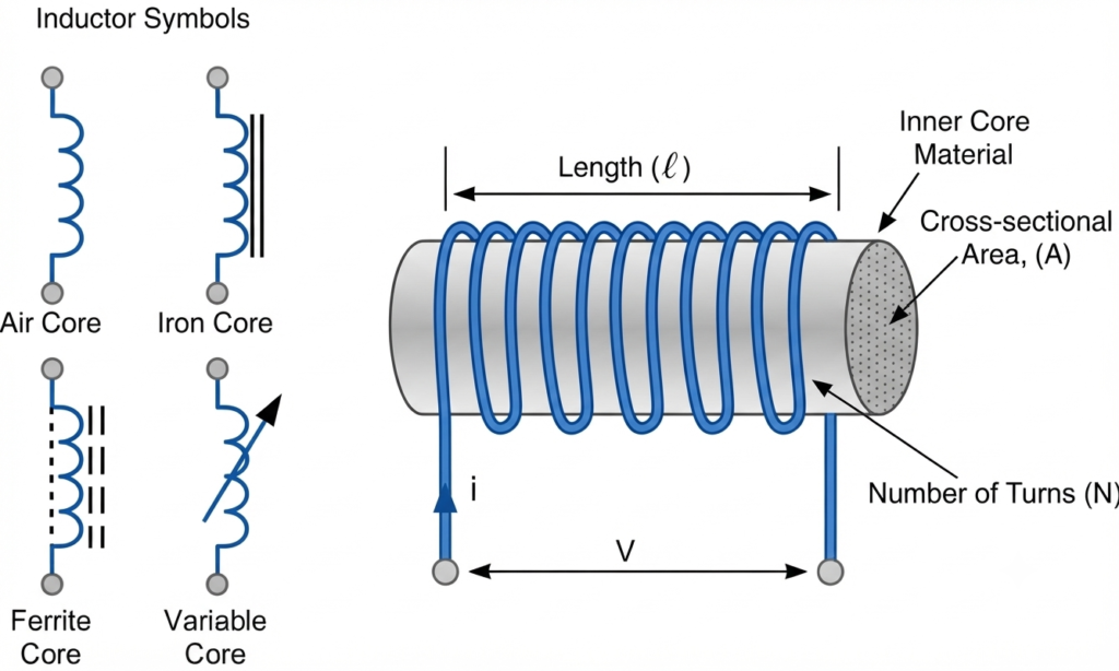
The schematic symbol of an inductor is represented by a series of curved loops that resemble the physical winding of a coil. When current flows through an inductor, it creates a magnetic field, and the associated magnetic flux increases or decreases with the current flowing through the winding.
Unlike a capacitor, which opposes changes in voltage, an inductor opposes changes in current. When the current through the coil changes, the changing magnetic field produces a self-induced voltage that acts against the change in current. This property is a direct consequence of electromagnetic induction.
In a steady-state DC circuit, an ideal inductor behaves approximately like a short circuit, allowing constant current to flow with no inductive voltage drop. However, when the current is increasing, decreasing, or changing direction, the inductor develops a voltage that opposes that change.
The ability of an inductor to oppose changes in current and establish a relationship between current and magnetic flux linkage is known as inductance. It is represented by the symbol L and measured in henries (H), named after the American scientist Joseph Henry.
The inductance of a coil depends on several factors, including the number of turns, core material, coil dimensions, and magnetic path. A higher inductance means the component produces a greater opposition to a given rate of change in current.
Inductance Prefixes
Since the henry is a relatively large unit, smaller units are commonly used to specify practical inductors:
| Unit | Symbol | Equivalent |
| Millihenry | mH | 1 mH = 10⁻³ H |
| Microhenry | µH | 1 µH = 10⁻⁶ H |
| Nanohenry | nH | 1 nH = 10⁻⁹ H |
Thus, an inductor marked 10 mH, for example, has an inductance of 0.01 H.
Inductance Units and Factors Affecting an Inductor
The henry (H) is the SI unit of inductance. Since practical inductors often have much smaller inductance values, sub-units such as millihenry and microhenry are commonly used.
For example:
- 1 mH (millihenry) = 0.001 H = one-thousandth of a henry
- 100 µH (microhenries) = 0.0001 H = one ten-thousandth of a henry
- 1 µH (microhenry) = 0.000001 H = one-millionth of a henry
The inductance of a coil depends on several physical and magnetic parameters. Important factors include the number of turns, coil shape and dimensions, spacing between turns, number of winding layers, core material, magnetic permeability, and the cross-sectional area of the core.
Consider a coil having N turns wound around a magnetic core with cross-sectional area A. When current flows through the winding, it establishes magnetic flux through the core. The total magnetic flux linkage of the coil is related to the number of turns and the magnetic flux through each turn.
The flux linkage can be expressed as:
where:
- λ = flux linkage in weber-turns (Wb-turn)
- N = number of turns in the coil
- Φ = magnetic flux in weber (Wb)
When the current through the coil changes, the magnetic flux also changes. According to Faraday’s law of electromagnetic induction, this changing flux linkage produces a self-induced voltage (EMF) across the winding. The induced voltage acts in a direction that opposes the change in current, in accordance with Lenz’s law.
The induced voltage can therefore be written as:
The negative sign indicates that the induced voltage opposes the change responsible for producing it. This is the fundamental principle behind the ability of an inductor to oppose changes in current.
Inductor Self-Induced Voltage Formula
When the current flowing through an inductor changes with time, the magnetic flux produced by the coil also changes. According to Faraday’s law of electromagnetic induction, this changing flux linkage generates a voltage across the coil. This voltage is called the self-induced EMF or back EMF because it acts in opposition to the change in current.
For a coil with a uniform magnetic core, the inductance can be expressed as:
where:
- L = inductance of the coil in henries (H)
- µ = permeability of the core material in H/m
- N = number of turns of the coil
- A = cross-sectional area of the core in m²
- ℓ = length of the magnetic path in meters
The flux linkage of the coil is related to its inductance and current by:
where Φ is the magnetic flux in webers (Wb) and i is the current through the coil in amperes (A).
Using Faraday’s law, the self-induced voltage is given by:
Since:
for a constant inductance, the equation becomes:
The negative sign represents Lenz’s law, indicating that the induced voltage opposes the change in current that produces it. Therefore, a faster change in current produces a greater induced voltage.
In magnitude form, the relationship is often written as:
This is one of the most important equations for understanding the behavior of an inductor in an electrical circuit.
Inductive Reactance
Inductive reactance is the opposition an inductor offers to alternating current (AC) due to the changing magnetic field produced by the current flowing through its coil. It depends on the inductance of the coil and the frequency of the AC supply. Higher inductance or frequency results in greater inductive reactance.
The formula for calculating inductive reactance is:
Where:
- = inductive reactance, measured in ohms (Ω).
- = frequency of the AC supply, measured in hertz (Hz).
- = inductance of the coil, measured in henries (H).
- = mathematical constant, approximately 3.1416.
Example: An inductor of 0.2 H is connected to a 50 Hz AC supply of 120 V. Calculate the rectance and current flowing through it.
The formula for inductive reactance is:
Substituting the given values:
The current flowing through the ideal inductor is:
Key point: At a frequency of 0 Hz (steady-state DC), the ideal inductive reactance is zero. As the AC frequency increases, the inductive reactance increases proportionally.
Impedance of an Inductor
Impedance of an inductor is a measure of the resistance offered by the alternating current (AC) passing through a circuit. In simple words, Impedance can be referred to as the opposition to the current passing in a circuit. Usually, it is denoted by ‘Z’. The standard measure for inductance is Ohm (Ω).
The formula for an inductor’s impedance is:
where,
Z is Impedance of the inductor
j is an imaginary unit
ω is the angular frequency of the AC signal
L is the inductance of the coil in Henry
Angular frequency is related to the supply frequency by:
Therefore, the impedance can also be expressed as:
The magnitude of an ideal inductor’s impedance is equal to its inductive reactance:
Key point: The impedance magnitude increases as either the inductance or AC frequency increases. For an ideal inductor supplied with steady-state DC, the frequency is zero, so its inductive impedance is zero. A practical inductor still has winding resistance and other non-ideal effects.
Back EMF Generated by an Inductor
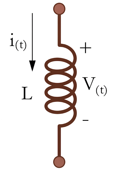
When the current flowing through an inductor coil changes, the resulting change in magnetic flux produces a voltage across the coil. This voltage is known as back EMF or self-induced EMF because it acts in a direction that opposes the change in current.
The magnitude of the induced voltage is expressed as:
where:
- V = induced voltage across the inductor in volts (V)
- L = inductance of the coil in henries (H)
- di/dt = rate of change of current in amperes per second (A/s)
Therefore, the relationship can be stated as:
The induced voltage is equal to the inductance multiplied by the rate of change of current.
For example, an inductor with an inductance of 1 H produces an induced voltage of 1 V when the current through it changes at a rate of 1 A/s.
An important feature of this equation is that an inductor responds to the change in current, rather than simply the presence of current. If the current remains constant, there is no change in magnetic flux and therefore no induced voltage. In a steady-state DC circuit:
and consequently:
Thus, after a DC circuit reaches steady state, an ideal inductor behaves like a short circuit, allowing constant current to flow without an inductive voltage drop. A practical inductor still has some winding resistance, so its actual behavior is closer to a low-resistance conductor.
The behavior is different in an AC circuit, where the current continuously changes with time. The inductor therefore continuously develops an induced voltage and opposes changes in current. This is why an inductor can offer significant opposition to AC while offering very little opposition to steady-state DC.
The Time Constant of an Inductor
The current through an inductor cannot change instantaneously. An abrupt change in current would require the current to change by a finite amount in zero time, making the rate of change of current extremely large:
Since the voltage across an inductor is related to the rate of change of current by:
a very rapid change in current can produce a very large induced voltage across the inductor.
In practical circuits, an ideal instantaneous change would require an unrealistically high, theoretically infinite voltage. However, real circuits always have some resistance, capacitance, switching limitations, and other parasitic effects that prevent truly infinite voltage. Nevertheless, a rapid step change in current, such as when a switch is suddenly opened or closed, can generate a significant voltage across the inductor.
The rate at which current rises or falls in an RL circuit is described by the inductive time constant. It determines how quickly the current approaches its final steady-state value.
For a simple series RL circuit, the time constant is:
where:
- τ = time constant in seconds (s)
- L = inductance in henries (H)
- R = resistance in ohms (Ω)
After one time constant (τ), the current reaches approximately 63.2% of its final value during an increasing-current transient. After about 5τ, the current is considered to have reached its steady-state value for most practical purposes.
Thus, the time constant of an inductor provides a useful measure of how quickly an RL circuit responds to a change in voltage or current.
Switching an Inductive Coil
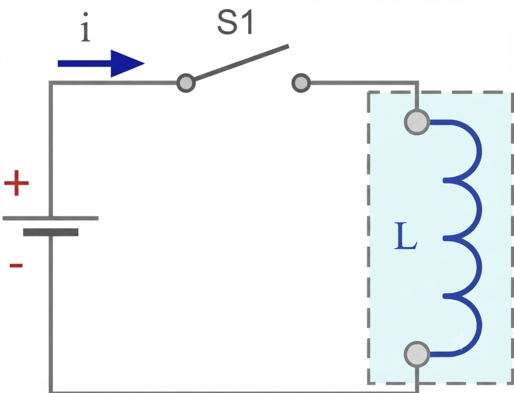
Consider a simple circuit containing an inductor coil and a switch. The behavior of the circuit changes significantly when the switch is opened or closed because an inductor always opposes a change in current.
When the switch S1 is open, no current flows through the inductor. Since the current remains at zero, there is no change in current with time:
Therefore, the voltage induced across the inductor is also zero:
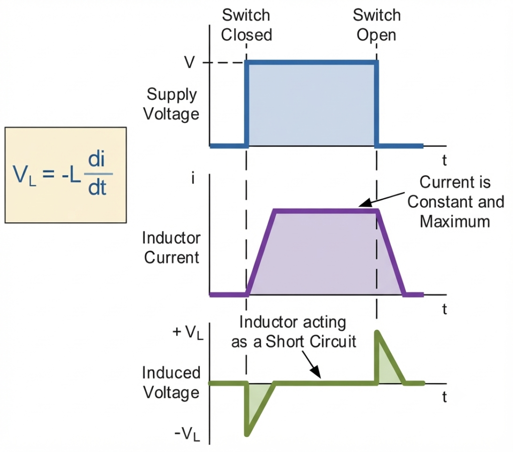
When the switch is closed at t = 0, current begins to flow through the circuit. Unlike a resistor, an inductor does not allow its current to rise instantaneously. Instead, the current increases gradually, with the rate of increase depending on the inductance and resistance of the circuit.
As the current increases, the magnetic field around the coil also builds up. This changing magnetic field produces a self-induced EMF that opposes the applied voltage and limits the rate at which the current rises. This behavior is described by:
The induced voltage gradually decreases as the rate of change of current becomes smaller. Once the circuit reaches steady-state DC conditions, the current becomes essentially constant:
Consequently, the ideal inductive voltage becomes zero. A practical inductor still has winding resistance, so the final current is primarily determined by the circuit resistance and the applied DC voltage. In this steady-state condition, the inductor itself behaves approximately like a low-resistance conductor.
The behavior is reversed when the switch S1 is opened. The current begins to decrease, but the inductor opposes this decrease and attempts to maintain the existing current. To do this, it generates an induced voltage with the opposite polarity to that produced during the current rise.
Because the current is now decreasing, its rate of change is negative. The magnitude of the induced voltage depends on how rapidly the current changes and on the inductance:
If the switch opens the circuit abruptly, the inductor may generate a large voltage spike because it attempts to keep the current flowing. This is an important consideration when switching inductive loads such as relays, contactors, solenoids, motors, and transformer windings. Protective components such as flyback diodes, RC snubbers, varistors, or surge suppressors are commonly used to control these switching transients.
Current and Voltage in an Inductor
Inductor Voltage and Lenz’s Law
The magnitude of the voltage induced across an inductor depends on how rapidly the current through the coil changes. The faster the current changes, the greater the induced voltage. This behavior is explained by Lenz’s law, which states that the direction of an induced EMF is always such that it opposes the change responsible for producing it.
In an inductor, the magnetic field produced by the current changes whenever the current changes. The resulting induced voltage acts against this change, thereby resisting a sudden increase or decrease in current. This is why an inductor naturally opposes rapid variations in current.
When the current through the coil is increasing, the induced voltage opposes the applied source and acts against the rise in current. When the current is decreasing, the inductor reverses its voltage polarity and acts in a way that supports the existing current, attempting to keep the current flowing.
Therefore, for the same magnitude of rate of current change, the magnitude of the induced voltage is the same whether the current is increasing or decreasing. The difference is the polarity and direction of the induced voltage, which are determined by Lenz’s law.
Inductor Tutorial: Worked Example No. 1
A steady-state DC current of 6 A flows through a solenoid having an inductance of 0.8 H. If the switch is opened and the current falls from 6 A to 0 A in 15 ms, calculate the average back EMF induced across the coil.
Given:
- Initial current,
- Final current,
- Inductance,
- Time interval,
The average induced voltage is:
Substituting the values:
Therefore, the average back EMF induced across the inductor is 320 V.
The actual polarity of this induced voltage will oppose the decrease in current, in accordance with Lenz’s law.
Instantaneous Power and Energy Stored in an Inductor
An ideal inductor has inductance but no electrical resistance. Therefore, it does not dissipate electrical energy as heat. Instead, it stores energy in its magnetic field when the current increases and returns that energy to the circuit when the current decreases.
The instantaneous power absorbed by an inductor is calculated using:
For an ideal inductor, the voltage-current relationship is:
Substituting this into the power equation gives:
The instantaneous power can be positive or negative, depending on whether the inductor absorbs energy from the source or returns stored energy to the circuit.
Although the instantaneous power is not always zero, the average power consumed by an ideal inductor over a complete AC cycle is zero. This is because the energy stored in the magnetic field is returned to the circuit during another part of the cycle.
In a practical inductor, the winding has some resistance, which causes power loss in the form of heat. Therefore, unlike an ideal inductor, a real inductor can consume electrical power.
The Energy Stored in an Inductor Coil
When current flows through an inductor, energy is stored in the magnetic field created around its coil. As the current increases, the magnetic field builds up and the inductor absorbs energy from the external source. When the current decreases, the stored magnetic energy can be returned to the circuit.
Because an inductor generates a self-induced EMF that opposes a change in current, the external source must supply energy to increase the current. The instantaneous electrical power associated with an inductor is determined from the basic power relationship:
For an inductor, the voltage magnitude is:
Therefore, the instantaneous power absorbed by the inductor is:
Substituting the voltage equation:
Thus, the instantaneous power of an inductor is:
where:
- P = instantaneous power in watts (W)
- L = inductance in henries (H)
- i = instantaneous current in amperes (A)
- di/dt = rate of change of current in amperes per second (A/s)
The power is positive when the inductor is absorbing energy and its magnetic field is building. When the current decreases, the stored energy is released back into the circuit, so the inductor can deliver energy to the surrounding circuit.
The energy stored in an inductor can be obtained by integrating its instantaneous power:
Since:
the stored energy becomes:
For a constant inductance, this gives:
Therefore, the energy stored in an inductor is proportional to its inductance and to the square of the current flowing through it. The stored energy is measured in joules (J).
Inductor Tutorial: Worked Example No. 2
An inductor of inductance 6 H carries a current of 4 A. Calculate the energy stored in it.
Solution:
The formula for energy stored in an inductor is:
Substituting the given values:
Therefore, the energy stored in the inductor is 48 joules (J).
Average Power in an AC Circuit
In a pure AC circuit containing an ideal inductor, energy continuously moves between the inductor’s magnetic field and the external circuit. During part of each AC cycle, the inductor absorbs energy and stores it in its magnetic field. During another part, it returns the stored energy to the source.
The instantaneous power absorbed by an inductor is:
Because the inductor alternately absorbs and returns energy, its average power over one complete AC cycle is zero. This assumes an ideal inductor with no winding resistance or other losses.
For sinusoidal AC, the average power can also be expressed as:
For an ideal inductor, the current lags the voltage by Therefore:
Inductors are classified as passive components because they can store and return energy but cannot generate energy independently. An ideal inductor has no internal power loss and can theoretically retain energy in its magnetic field indefinitely if its current remains constant.
However, practical inductors have winding resistance, which causes electrical energy to be converted into heat whenever current flows through the coil. The resistive power loss is calculated using Joule’s law:
where is the RMS current for an AC circuit and is the winding resistance.
Therefore, while an ideal inductor consumes zero average power over a complete AC cycle, a real inductor consumes some power because of winding resistance and other losses, such as core losses.
Inductors in Parallel
When two or more inductors are connected in parallel, they share the same two connection points. Therefore, the voltage across each inductor is equal, while the total current divides among the parallel branches.
For ideal, uncoupled inductors, the equivalent inductance is lower than the smallest individual inductance. This arrangement can be used when a circuit requires a lower overall inductance.
The total inductance of inductors connected in parallel is calculated using the following formula:
Where:
- is the total or equivalent inductance, measured in henries (H).
- are the individual inductances, measured in henries (H).
- is the total number of inductors connected in parallel.
For two inductors, the formula can be simplified to:
Derivation of the Parallel Inductance Formula
Step 1: Apply Kirchhoff’s Current Law
The total current entering the parallel combination equals the sum of the branch currents.
Step 2: Apply the inductor voltage equation
The voltage across an ideal inductor is given by:
Since all inductors are connected across the same two terminals, their voltages are equal:
Substituting the total current equation gives:
Expanding the derivative:
Step 3: Substitute the branch current derivatives
For each ideal inductor,
Therefore,
Dividing both sides by \(V\), for nonzero voltage, gives:
Hence, the equivalent inductance is:
Important note: This formula assumes the inductors are magnetically uncoupled. If their magnetic fields interact, the mutual inductance must also be considered.
Example: Two inductors of 3 H and 9 H are connected in parallel. Find the total inductance.
The formula for total inductance of two inductors connected in parallel is:
Substituting the given values:
Therefore,
Hence, the total inductance is 2.25 H, assuming ideal, magnetically uncoupled inductors.
Inductors in Series
When two or more inductors are connected end-to-end, they form a series connection. The same current flows through every inductor, while the voltage across each component depends on its inductance and the rate of change of current. For ideal, magnetically uncoupled inductors, the total inductance is equal to the sum of their individual inductances.
The total inductance of inductors connected in series is given by following formula:
Where:
- is the total or equivalent inductance, measured in henries (H).
- are the individual inductances, measured in henries (H).
- is the total number of inductors connected in series.
Derivation of the Series Inductance Formula
Step 1: Determine the current relationship
In a series circuit, the same current flows through every inductor.
Step 2: Apply Kirchhoff’s Voltage Law
The total voltage across the series combination is the sum of the individual inductor voltages.
The voltage across an ideal inductor is expressed as:
Therefore,
Substituting the voltage equation for each inductor gives:
Step 3: Substitute the common current
Since the current is the same through every inductor, their current derivatives are also equal:
Thus,
Canceling the common current derivative gives the final result:
Important note: This formula assumes there is no significant mutual magnetic coupling between the inductors. If their magnetic fields interact, the equivalent inductance also depends on mutual inductance and the relative winding directions.
Example: Two inductors of 3 H and 9 H are connected in series. Find the total inductance.
The formula for the total inductance of inductors connected in series is:
Substituting the given values:
Hence, the total inductance of the series combination is 12 H, assuming there is no significant mutual magnetic coupling between the inductors.
Types of Inductors
Inductors are classified according to their core material, construction, and intended application. Each type offers different inductance, frequency response, and energy-loss characteristics.
1. Iron Core Inductor: Uses an iron core to achieve high inductance and is suitable for power applications operating at relatively low frequencies. However, core losses can make conventional iron-core inductors less suitable for high-frequency circuits.
2. Air Core Inductor: Uses air as the magnetic medium instead of a solid core. It has low core losses and performs well at high frequencies, making it useful in radio-frequency circuits, tuning circuits, and oscillators.
3. Iron Powder Core Inductor: Uses a core made from compressed iron powder mixed with a binding material. It offers controlled inductance, good energy-storage capability, and relatively low core losses over suitable frequency ranges. Common applications include switching power supplies, filters, and DC-DC converters.
4. Ferrite Core Inductor: Uses ferrite, a magnetic ceramic material with high electrical resistivity. This helps reduce eddy-current losses, making ferrite-core inductors suitable for high-frequency power supplies, transformers, and electronic circuits.
5. Choke Inductor: Designed to impede alternating current (AC) while allowing direct current (DC) to pass with relatively low resistance. Chokes are commonly used in power-supply filters, electromagnetic interference (EMI) suppression, and noise-reduction circuits.
Applications of an Inductor
Inductors are widely used in electrical and electronic circuits because of their ability to store energy in a magnetic field and oppose changes in current. Their properties make them useful in filtering, power conversion, signal processing, and electromagnetic interference suppression.
The major applications of inductors include:
- Filter circuits: Inductors work with capacitors to form low-pass, high-pass, and other filter circuits that control unwanted frequencies and electrical noise.
- Resonant circuits: When combined with capacitors, inductors form LC circuits used in tuning circuits, radio receivers, and frequency-selective networks.
- Oscillators: Inductors and capacitors help establish the resonant frequency in LC oscillators used to generate periodic electrical signals.
- Power supplies: Inductors are essential components in switching power supplies and DC-DC converters, where they store and transfer energy during switching cycles.
- Current smoothing: Inductors reduce current fluctuations and ripple in rectifier circuits and power converters.
- Voltage spike suppression: Inductors and associated protection circuits help manage switching transients. Additional protective components may be required to clamp dangerous voltage spikes.
- Chokes and noise suppression: Inductors are used to restrict unwanted high-frequency currents and reduce electromagnetic interference in electrical equipment.
- Energy storage: Inductors temporarily store energy in their magnetic fields and release it when required by the circuit.
Inductor vs Capacitor
An inductor and a capacitor are passive electrical components that store energy in different forms and respond differently to changes in current and voltage. The following table highlights their main differences.
| Inductor | Capacitor |
| Opposes changes in current through the component. | Opposes changes in voltage across the component. |
| Stores energy in a magnetic field. | Stores energy in an electric field. |
| Inductance is measured in henries (H). | Capacitance is measured in farads (F). |
| In an ideal AC circuit, current lags voltage by 90° (π/2 radians). | In an ideal AC circuit, current leads voltage by 90° (π/2 radians). |
| Inductive reactance increases with frequency. | Capacitive reactance decreases with frequency. |
| Commonly used in chokes, filters, and switching power supplies. | Commonly used in coupling circuits, decoupling circuits, and energy-storage applications. |
Note: Neither component is inherently more efficient at low or high frequencies. Their suitability depends on the circuit design, component characteristics, operating frequency, and application.
Conclusion
An inductor is a passive electrical component that stores energy in its magnetic field and opposes changes in current flowing through it. Its main characteristic, known as inductance, is measured in henries (H) and depends on factors such as the number of coil turns, core material, and coil dimensions.
The inductor’s operation is based on Faraday’s law of electromagnetic induction and Lenz’s law, which explain how a changing current produces an induced voltage that opposes the change. An ideal inductor consumes zero average power over a complete AC cycle, while a practical inductor experiences losses due to winding resistance and magnetic effects.
Because of these properties, inductors play an important role in power supplies, filter circuits, oscillators, current smoothing, and noise suppression. Understanding their behavior helps in designing efficient and reliable electrical and electronic circuits.
Read Next:
- AC Capacitance: Formula, Reactance & Phase Angle
- Resistors in Series: Definition, Formula, Rules, Calculation, and Examples
- Capacitors in Series and Series Capacitor Circuits – Complete Guide
- Resistors in Parallel – Parallel Connected Resistors Explained
- Voltage Divider: Rule, Equations, Formulas, and Practical Applications
- Inductance of a Coil: Formula, Factors & Examples
- Inductors in Series: Formula, Examples & Mutual Inductance
- Mutual Inductance: Definition, Formula, Unit, Coupling Coefficient & Examples