A passive averager provides a simple way to obtain an average value from a varying electrical signal using only passive components. Its operation depends on the interaction of resistors and capacitors, making it useful in signal conditioning and basic analog circuits.
What Is a Passive Averager Circuit?
A Passive Averager Circuit uses a network of passive resistors to combine two or more input voltages and produce an output voltage equal to their mathematical average. Since it does not use an active amplification stage, the circuit provides averaging without voltage gain.
In the tutorial on summing amplifier, we saw how multiple input voltages can be combined using an inverting operational amplifier to produce a single output signal. Depending on the configuration, the output can represent either an inverted or non-inverted sum of the applied input signals.
A summing amplifier can also apply a different gain to each input. This gain is determined by the ratio of the feedback resistor to the corresponding input resistor .
When all the input resistors have the same value, the circuit performs direct summation, giving each input the same weight. In contrast, a binary-weighted summing amplifier uses input resistors with different values, typically doubling each successive resistor value to produce different weights for the input signals. Summing amplifiers are widely used in applications such as audio mixers and analogue-to-digital converters (ADCs).
In addition to performing addition or subtraction, multiple-input circuits can also be arranged to perform averaging. An averager circuit produces an output voltage corresponding to the average value of two or more input voltages. A passive averager achieves this function using only a resistive network, without requiring an operational amplifier for amplification.
Passive Averager Circuit
A Passive Averager is a resistive network designed to produce an output voltage equal to the mathematical average of two or more input voltages. An averager circuit can be built with any number of inputs using either passive or active components. Let us first consider the basic two-input resistive circuit shown below.
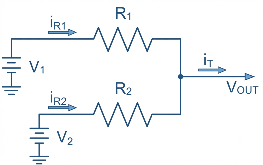
Here, resistors and are connected at one end to a common junction or node, while the other end of each resistor is connected to a separate voltage source.
This simple arrangement forms a passive averager circuit, in which the input voltages interact through the resistors to produce an output voltage at the common junction. The same basic resistive arrangement can also be used in summing and subtractor circuits.
Kirchoff’s Current Law (KCL) states that the algebraic sum of all currents entering and leaving a circuit junction or node is equal to zero.
Therefore, the total current in this passive resistive circuit can be expressed as:
Voltage Output Derivative
Therefore,
This means that is determined by the sum of the input currents divided by the total conductance of the connected resistors. Since the resistors are effectively connected in parallel through their respective voltage sources, this relationship forms the basis of Millman’s Theorem.
Using conductance , the basic relationship can be expressed as:
where represents conductance.
The two-input passive averager equation can then be extended to resistive circuits having three, four, or more input resistors and voltage sources, as shown below.
Passive Averager Equation
The general equation for a Passive Averager Circuit is shown in the image below.
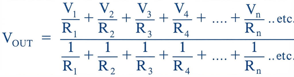
This means that any number of input voltages can be connected through the corresponding resistors to form a passive averager. When the input resistors have equal values, the voltage at the common output node represents the mathematical average of all the applied input voltages.
Passive Averager Worked Example No. 1
A 2-input passive averager circuit is constructed using a 3 kΩ and a 6 kΩ resistor connected together. If a 15 V DC voltage source is connected to one end of the 3 kΩ resistor and a second 9 V DC voltage source is connected to one end of the 6 kΩ resistor, calculate the output voltage at the common junction.
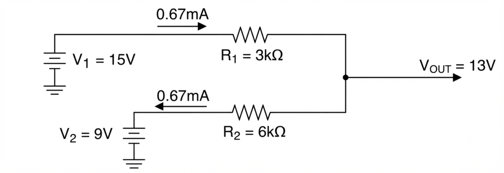
So the common junction voltage is calculated as 13 volts. However, you may notice that:
Therefore, the simple mathematical average of the two input voltages is 12 V.
The reason the circuit produces 13 V is that the two resistors have different values, and . These unequal resistance values cause different currents to flow through the two branches, producing what is known as a Weighted Averager Circuit. In other words, each input voltage is given a different weighting factor before the averaging takes place.
For this example, the current through is:
The current through is:
Thus, approximately 0.667 mA flows from the higher 15 V supply toward the lower 9 V supply through the common junction.
Passive Averager Equation when R1 =R2
However, if both input resistors are made equal, such that:
then the currents associated with the two inputs have equal resistance weighting. The passive averager equation then simplifies to the ordinary arithmetic average of the input voltages:
When the two input resistors have equal values, each input voltage receives the same weighting. Therefore, the voltage at the common junction becomes exactly equal to the arithmetic average of the two input voltages, making it a true Passive Averager Circuit.
Using our example values, if:
and
then:
Therefore, with equal resistance values, the output voltage at the common junction is 12 volts, which is exactly the average of the two input voltages.
Passive Averager Worked Example No. 2
A 4-input passive averager circuit is constructed using the following resistor values: , , , and . The corresponding input voltages applied to these resistors are , , , and .
Calculate the output voltage of the passive resistive network. Then calculate the output voltage when all four resistors have equal resistance values.
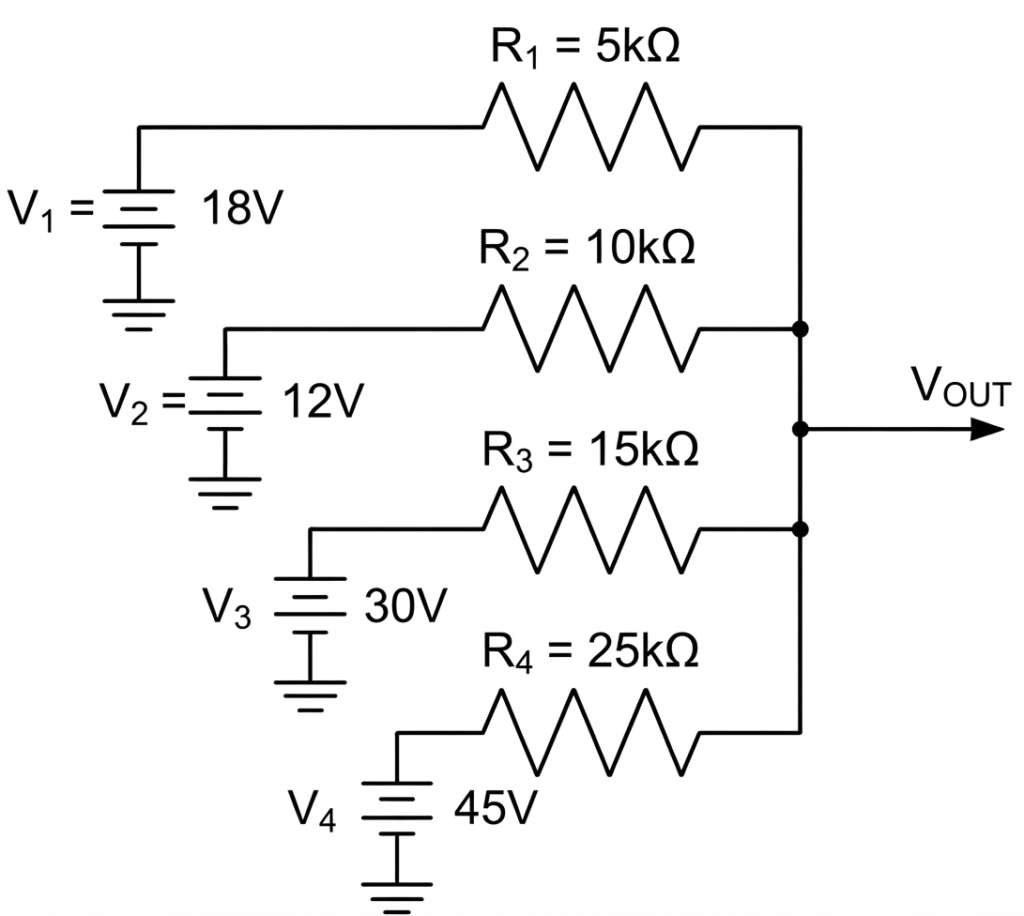
The output voltage is:
With all resistor values being equal and represented by :
The passive averager equation becomes:
We can see that the values of the individual resistors have a significant effect on the output voltage, . In our example, the weighted average voltage was calculated as approximately 21.15 V, whereas the true average voltage with all resistors having equal values was calculated as 26.25 V.
Both cases are useful because the first method forms the basis of Millman’s Theorem, in which any number of parallel resistive and voltage branches can be reduced to a single equivalent voltage value. For our example, the four voltage sources with unequal resistance values produce a single output voltage of approximately 21.15 V.
When all four resistors have equal values, the circuit becomes a true Passive Averager Circuit, and the output voltage is the arithmetic average of the four input voltages, giving 26.25 V.
Operational Amplifier Averager Circuit
One of the main disadvantages of a passive averager circuit is that it consists only of a resistive network and therefore provides no isolation from the connected load. As a result, the output voltage can be affected by the loading effect, particularly when the load has a low impedance.
This problem can be overcome by converting the passive averager into an active averager circuit. This can be done by connecting a Non-inverting Operational Amplifier to the output of the resistive averaging network.
The simplest approach is to connect the output of the resistive averager network to an operational amplifier configured as a voltage follower. A voltage follower acts as a unity-gain buffer, providing a high input impedance and a low output impedance while maintaining the averaged voltage at its output.
Averager Circuit Using an Op-Amp
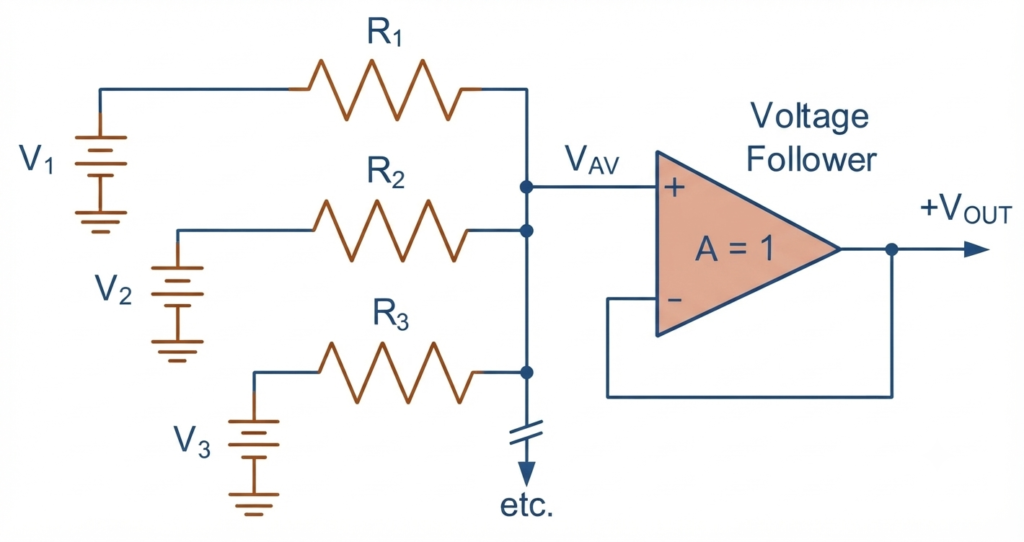
An op-amp has a very high input impedance, so practically no current flows into its non-inverting input terminal. Since the op-amp output is directly connected to its inverting input, the circuit provides 100% negative feedback. As a result, the input voltage is equal to the output voltage, giving the op-amp a fixed gain of 1, or unity gain.
Therefore:
This configuration produces a positive-output averager circuit. The main advantage is that the op-amp provides isolation between the input resistive network and the connected load. Consequently, the averaging operation is not significantly affected by the load, and any number of inputs can be connected to the averaging network.
The Inverting Op-Amp Averager
The operational amplifier can also be configured as an inverting amplifier to obtain an average output voltage with polarity opposite to the input signals. The closed-loop voltage gain, , is determined by the feedback network connected between the op-amp output and its inverting input. It is given by:
Then, this expression can be rearranged to give:
For an averaging amplifier, represents the combined input signal. Therefore, for a simple 3-input averager, the output voltage expression can be written as:
Thus, each input voltage is scaled by the same factor, . If all the input resistors and the feedback resistor have the same value, , and we use three input signals, then:
and
Substituting these values into the above equation, the output voltage becomes:
When the closed-loop voltage gain of the operational amplifier is set to the reciprocal of the number of inputs, which is for this three-input example, the inverting op-amp averager produces an output equal to the mathematical average of the three input voltages, with the polarity inverted. Thus, the output is , as shown.
Inverting Averager Circuit
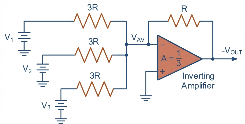
In this simple inverting op-amp Averager Circuit, three input signals are used. However, the circuit can be designed with any number of inputs to meet the requirements of a particular application.
For proper averaging, all input resistors must have the same value of . Here, is the resistance of the feedback resistor, is the total number of input channels, and is the resistance of each individual input resistor. This resistor relationship ensures that the circuit produces the average of the input voltages. If the input resistors do not follow this relationship, the circuit operates as a summing amplifier rather than an averaging amplifier.
Conclusion
A Passive Averager provides a simple way to obtain the average of multiple input voltages using a resistive network, without requiring an external power supply or active amplification. When equal-value resistors are used, the voltage at the common output point represents the mathematical average of the applied inputs. With unequal resistor values, the circuit produces a weighted average, which forms the basis of Millman’s theorem.
An op-amp averager overcomes the loading limitations of a passive resistor network by providing buffering and isolation at the output. It can be configured as a non-inverting voltage follower for a positive average output or as an inverting amplifier for a negative average output. In the inverting configuration, selecting the input resistors according to the number of inputs allows the circuit to produce the average of multiple signals with inverted polarity.
Overall, averaging circuits are useful in signal conditioning, analog computation, measurement systems, audio circuits, and other applications where multiple voltage signals need to be combined into a representative average value.
Read Next:
- Inverting vs Non-Inverting Amplifier: Differences, Gain, and Applications
- Inverting Operational Amplifier: Circuit, Working, and Gain Formula
- Op-Amp Building Blocks: Basic Circuits and Applications
- Operational Amplifier (Op-Amp): Basics, Types, Working & Applications
- Non-inverting Operational Amplifier: Circuit, Gain & Formula
- Summing Amplifier: Circuit, Gain Formula, Derivation & Applications
- Differential Amplifier: Circuit, Types, Formula & Applications
- Op-Amp Integrator Amplifier: Formula, Working & Applications
- Op-Amp Differentiator Amplifier: Circuit, Working, Formula & Applications
- Op-Amp Multivibrator: Working, Circuit, Types & Applications
- Op-Amp Comparator: Circuit, Working, Formula, Hysteresis & Applications
- Op-Amp Monostable Multivibrator: Circuit, Working, Formula & Timing