An Op-amp Multivibrator is widely used in electronic circuits where precise pulse generation, switching, and timing are required. By combining an operational amplifier with resistors and capacitors, the circuit can produce stable or continuously changing output waveforms. Its simple design and flexible timing characteristics make it useful in oscillators, pulse generators, timers, and other waveform-generating applications.
What Is an Op-amp Multivibrator?
An Op-Amp Multivibrator is an astable oscillator circuit that uses an operational amplifier, resistors, capacitors, and positive feedback to generate switching or oscillating waveforms. Depending on its configuration, it can produce square waves, rectangular pulses, or timing signals.
The circuit uses the high gain of the op-amp and a positive feedback network to switch the output between different voltage levels. A capacitor charges and discharges through a resistor, controlling the timing of these output transitions.
There are three main types of multivibrators: astable, monostable, and bistable. An astable multivibrator continuously generates a waveform, while a monostable multivibrator produces a single pulse for each trigger. A bistable multivibrator has two stable states and changes state when an external trigger is applied.
Because of these characteristics, Op-amp Multivibrators are widely used in oscillators, pulse generators, timers, frequency generators, switching circuits, and waveform-generation applications. The required timing and frequency can be adjusted by selecting suitable resistor and capacitor values.
Op-Amp Multivibrator Working Principle
The working principle of an Op-Amp Multivibrator is based on the continuous charging and discharging of a capacitor combined with positive feedback. A basic astable circuit can generate a rectangular output waveform using only three resistors and one timing capacitor, along with the operational amplifier.
In this configuration, the RC timing network is connected to the inverting input of the op-amp, while a resistor voltage-divider network is connected to the non-inverting input. The RC network determines how quickly the capacitor voltage changes, whereas the voltage-divider network establishes the switching levels for the circuit.
The circuit operates as an astable multivibrator, which means that it has two output states but neither state is stable. The output continuously changes from one state to the other. As the capacitor charges and discharges through the timing resistor, its voltage repeatedly reaches the switching thresholds, causing the op-amp output to change state. This process continues automatically and produces a continuous rectangular waveform.
Op-Amp as a Comparator
During operation, the op-amp essentially functions as a voltage comparator. It continuously compares the voltages applied to its inverting and non-inverting inputs. When the voltage at one input becomes higher or lower than the reference level at the other input, the op-amp changes its output polarity.
In an idealized open-loop configuration, the output can move toward either the positive saturation voltage, , or the negative saturation voltage, . Therefore, even a small difference between the two input voltages can cause a significant change in the output.
However, an open-loop op-amp is extremely sensitive when the two input voltages are close to each other. Small voltage fluctuations or electrical noise around the reference level can cause unwanted or rapid changes in the output. Such uncontrolled switching is undesirable in a multivibrator circuit.
Schmitt Trigger Action in an Op-Amp Multivibrator
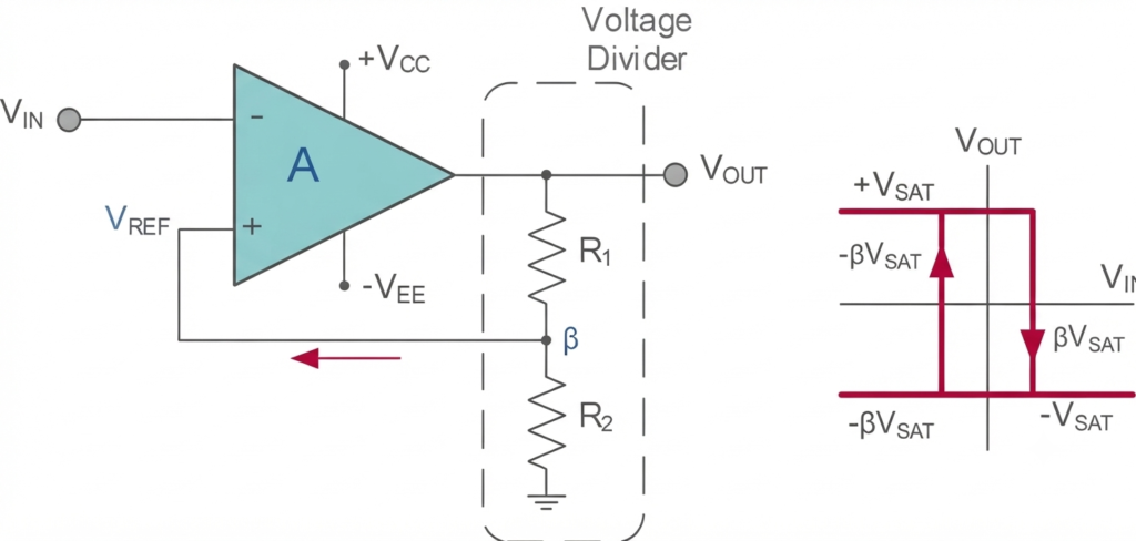
To provide controlled switching, the op-amp is configured with positive feedback, forming a Schmitt Trigger. The feedback network creates two distinct switching thresholds instead of a single reference level.
As the timing capacitor charges, its voltage gradually approaches one of these thresholds. When the threshold is reached, the op-amp switches to the opposite saturation state. The capacitor then begins discharging in the opposite direction until it reaches the other threshold. This causes the output to switch back again.
The charging and discharging process therefore repeats continuously. The interaction between the RC timing network and the Schmitt Trigger determines the oscillation frequency and produces the rectangular output waveform.
This combination of positive feedback and RC timing makes the Op-Amp Multivibrator a simple and effective circuit for generating repetitive waveforms, timing signals, and switching pulses.
Positive Feedback and Hysteresis
In an Op-Amp Multivibrator, the op-amp comparator is configured as a Schmitt Trigger by using positive feedback through resistors and . This feedback introduces hysteresis, which gives the circuit two different switching threshold levels.
The resistive feedback network is connected between the op-amp output and its non-inverting input. Therefore, the voltage applied to the non-inverting input depends on the present state of the op-amp output.
When the output reaches its positive saturation level, , a positive voltage is fed back to the non-inverting input. When the output switches to the negative saturation level, , the feedback voltage at the non-inverting input also becomes negative.
The two resistors form a voltage-divider network, so only a fraction of the output voltage is returned to the non-inverting input. This fraction determines the reference voltage used by the Schmitt Trigger for switching.
As the output changes from positive to negative saturation and back again, the feedback voltage changes between two corresponding threshold levels. These separate thresholds prevent unwanted switching caused by small voltage fluctuations and provide stable, controlled transitions.
The fraction of the output voltage returned to the non-inverting input is known as the feedback fraction, β. Its relationship with the two resistors is discussed in the following section.
Feedback Fraction (β) Equation
Therfore,
Here, represents the positive DC saturation voltage of the op-amp, while represents the negative DC saturation voltage.
Reference Voltages and Hysteresis
The feedback fraction determines the two reference levels of the Schmitt Trigger. When the output of the op-amp is at its positive saturation voltage, the non-inverting input receives a positive reference voltage. This is the upper reference voltage, .
Similarly, when the op-amp output switches to its negative saturation voltage, the feedback voltage at the non-inverting input becomes negative. This produces the lower reference voltage,.
Therefore, the two reference levels are related to the op-amp saturation voltage and the feedback fraction by:
and
These two reference voltages determine when the op-amp changes its output state.
When the input voltage rises above the upper reference voltage, , the op-amp switches its output from the positive saturation level to the negative DC saturation voltage. On the other hand, when falls below the lower reference voltage, , the op-amp switches again, changing its output from the negative saturation level back to the positive DC saturation voltage.
Thus, the circuit has two different switching points rather than a single threshold. The voltage difference between these upper and lower reference levels is called the hysteresis voltage. It defines the range over which the input voltage can change without causing another output transition.
The hysteresis voltage is therefore given by:
A suitable amount of hysteresis helps the Op-Amp Multivibrator achieve reliable switching and prevents unwanted output transitions caused by small fluctuations around the switching threshold.
Sinusoidal to Rectangular Converter
An Op-Amp Multivibrator can also be used as a sinusoidal-to-rectangular waveform converter. In this application, a periodic sine-wave signal is applied to the input of the Schmitt Trigger circuit. When the input amplitude is sufficiently higher than the reference voltage, , the op-amp switches between its positive and negative saturation levels as the input crosses the two threshold voltages.
Because the input signal is periodic, the output also becomes a periodic rectangular waveform. The output waveform has the same time period, T, and frequency, f, as the input sinusoidal signal. However, its waveform shape is changed from sinusoidal to rectangular because of the switching action of the Schmitt Trigger.
The switching point can also be adjusted by making either or variable, such as by replacing one of them with a potentiometer. Adjusting the potentiometer changes the feedback fraction, , and consequently changes the reference voltage applied to the non-inverting input.
This adjustment changes the point on the input sine wave at which the op-amp changes state. The switching angle can be varied from approximately 0° to 90° of each half-cycle, provided that the selected reference voltage remains below the maximum amplitude of the input signal.
This makes the circuit useful when a clean rectangular waveform is required from a sinusoidal input while allowing the switching threshold to be adjusted according to the application.
Basic Op-Amp Multivibrator
The concept of converting a periodic waveform into a rectangular output can be extended by replacing the sinusoidal input with an RC timing circuit connected to the op-amp output.
In this arrangement, the sinusoidal signal is no longer used to trigger the op-amp. Instead, the charging voltage of the capacitor, , changes continuously and causes the op-amp output to switch between its states, as shown in the circuit.
Op-amp Multivibrator Circuit
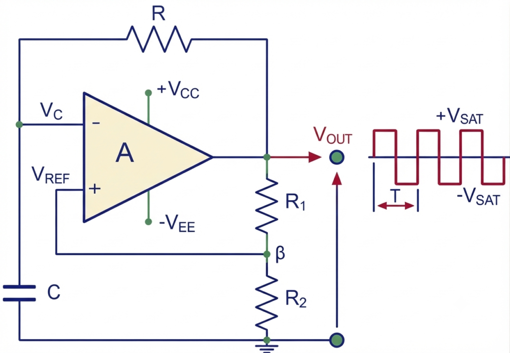
To understand the operation of this basic Op-Amp Multivibrator circuit, assume initially that the capacitor is completely discharged and the op-amp output is at its positive saturation level, . The capacitor then begins charging through resistor toward the output voltage. The charging rate is determined by the RC time constant of the circuit.
As in a conventional RC charging circuit, the capacitor voltage gradually approaches the applied output voltage, . However, the charging process does not continue indefinitely. When the capacitor voltage at the op-amp’s inverting input reaches the reference voltage at the non-inverting input, the op-amp switches its output state.
The output therefore changes from to the negative saturation level, . The capacitor, which was previously charging toward the positive saturation voltage, now has the negative saturation voltage applied through resistor .
As a result, the capacitor starts discharging toward the new negative output voltage. The discharge occurs according to the same RC time constant. When the capacitor voltage reaches the opposite switching threshold, the op-amp changes state again, and the cycle repeats continuously.
Op-amp Multivibrator Voltages Waveform
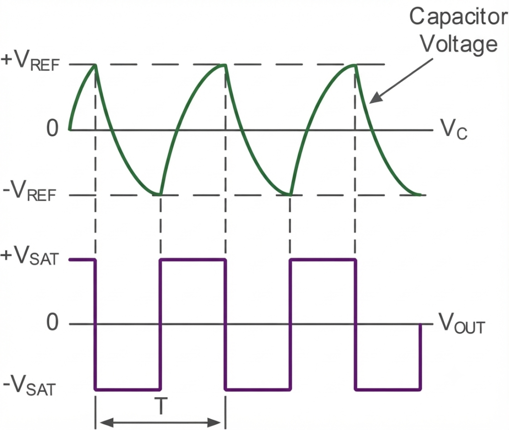
When the capacitor voltage reaches the negative reference level, , at the op-amp’s inverting input, the comparator changes state again. The output switches from the negative saturation voltage, , back to the positive saturation voltage, .
The capacitor now has a positive voltage applied across it and begins charging in the opposite direction. This charging process continues until the capacitor voltage reaches the other switching threshold. The op-amp then changes state again, and the cycle repeats continuously.
Therefore, the capacitor repeatedly charges and discharges between the upper and lower reference voltages, while the op-amp output alternates between its positive and negative saturation levels. This continuous process produces the rectangular output waveform shown in the figure and forms the basis of the astable Op-Amp Multivibrator.
The period of oscillation depends on the RC timing network and the feedback fraction established by the voltage-divider network. The RC network controls the capacitor charging and discharging time, while the feedback network determines the reference voltage levels at which the op-amp switches state.
When the positive and negative saturation voltages have equal magnitudes, the charging and discharging intervals are equal, so:
In this case, the total period of oscillation can be expressed using the corresponding timing relationship.
Oscillation Period and Frequency
Where is the timing resistance, is the timing capacitance, denotes the natural logarithm, is the oscillation period in seconds, and is the oscillation frequency in hertz (Hz).
The equation shows that the oscillation frequency depends on . Therefore, changing either the timing components or the resistor-divider values can affect the operating frequency.
For a feedback fraction of approximately 0.462, or , the logarithmic term becomes approximately equal to 1. Under this condition, the period simplifies to approximately , giving an oscillation frequency of:
This provides a simple approximation for selecting the timing components when designing an Op-Amp Multivibrator.
Worked Example No. 1
An Op-Amp Multivibrator circuit is constructed using the following components: , , , and . Calculate the astable circuit’s frequency of oscillation.
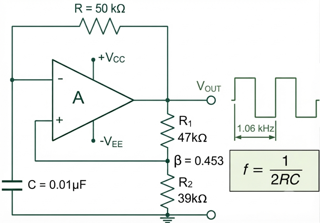
Solution:
Given:
First, calculate the feedback fraction :
The period of oscillation is:
Therefore, the frequency of oscillation is:
Frequency Calculation and Circuit Adjustment
For the component values used in the above example, the feedback fraction is , giving an oscillation frequency of approximately 1.02 kHz. The frequency is calculated using the complete astable multivibrator equation because the feedback fraction is not exactly 0.462.
If the two feedback resistors are made equal, that is, , the feedback fraction becomes . In this case, the frequency of oscillation can be approximated as:
The Op-Amp Multivibrator can also be modified to provide an adjustable output frequency by replacing one of the feedback resistors with a potentiometer. Adjusting the potentiometer changes the feedback fraction and, consequently, the oscillation frequency of the circuit.
Variable Op-amp Multivibrator
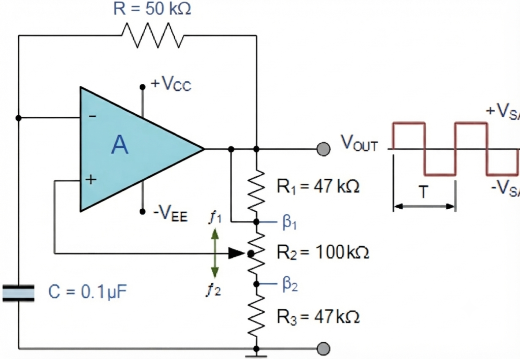
By adjusting the central potentiometer between the and positions, the feedback fraction changes, allowing the output frequency of the Op-Amp Multivibrator to be varied between the corresponding frequency limits.
Potentiometer at Position β1
Now,
Therefore,
Potentiometer at Position β2
At the other position, the effective feedback resistance is;
Therefore,
Therefore,
Thus, by adjusting the 100 kΩ potentiometer, the variable Op-Amp Multivibrator can provide an output frequency approximately from:
So, the circuit produces a variable rectangular waveform from approximately 0.5 kHz to 2.0 kHz.
Thus, with , , , , and , the Variable Op-Amp Multivibrator can generate a rectangular output waveform over a frequency range of approximately 504 Hz to 2.03 kHz. The output frequency can be adjusted by moving the potentiometer and changing the feedback fraction.
We have seen that an astable multivibrator can be constructed using a standard operational amplifier, a timing resistor and capacitor, and a feedback resistor network with a potentiometer. The continuous charging and discharging of the timing capacitor causes the op-amp output to switch between its positive and negative saturation levels, producing a continuous rectangular waveform.
The practical frequency range of an Op-Amp Multivibrator depends on the selected RC timing components, feedback network, and the characteristics of the operational amplifier. For higher-frequency operation, the op-amp’s bandwidth and slew rate must also be considered.
Conclusion
The Op-Amp Multivibrator is a simple and versatile circuit for generating rectangular and pulse waveforms. Its operation combines positive feedback, Schmitt Trigger action, and an RC timing network to produce continuous switching at the op-amp output.
The astable configuration continuously switches between its positive and negative saturation levels as the timing capacitor charges and discharges between the upper and lower reference voltages. The feedback fraction determines the switching thresholds, while the RC time constant primarily controls the oscillation period and frequency.
The circuit can also be used as a sinusoidal-to-rectangular waveform converter and can be modified with a potentiometer to obtain a variable-frequency output.
The Op-Amp Multivibrator is useful in oscillators, pulse generators, timing circuits, switching applications, and waveform-conversion circuits.
Read Next:
- Inverting vs Non-Inverting Amplifier: Differences, Gain, and Applications
- Inverting Operational Amplifier: Circuit, Working, and Gain Formula
- Op-Amp Building Blocks: Basic Circuits and Applications
- Operational Amplifier (Op-Amp): Basics, Types, Working & Applications
- Non-inverting Operational Amplifier: Circuit, Gain & Formula
- Summing Amplifier: Circuit, Gain Formula, Derivation & Applications
- Differential Amplifier: Circuit, Types, Formula & Applications
- Op-Amp Integrator Amplifier: Formula, Working & Applications
- Op-Amp Differentiator Amplifier: Circuit, Working, Formula & Applications
- Op-Amp Comparator: Circuit, Working, Formula, Hysteresis & Applications
- Op-Amp Monostable Multivibrator: Circuit, Working, Formula & Timing