Inductors can be connected in series by connecting them end to end in a single electrical path. In this configuration, the same current flows through every inductor, while the total voltage across the combination equals the sum of the individual voltage drops. For ideal inductors with no significant mutual coupling, the total inductance is equal to the sum of their individual inductances.
Connecting Inductors in Series
Connecting uncoupled inductors in series means connecting them end to end in a single electrical path. This arrangement increases the total inductance compared with using any one of the inductors individually.
When there is no significant mutual inductance or magnetic coupling between the coils, the total inductance is equal to the sum of their individual inductances. This follows the same addition principle used to calculate the equivalent resistance of resistors connected in series.
The total inductance is given by:
Where is the total inductance and are the individual inductances.
Series Inductance
Connecting inductors and coils in different configurations creates electrical networks whose total inductance depends on the individual inductance values and their arrangement in the circuit.
Certain rules apply when connecting inductors in series or parallel, assuming the coils are not magnetically coupled. This means their magnetic fields do not significantly influence one another.
An inductor stores energy in its magnetic field when current flows through it. When inductors are connected in series, the same current passes through each inductor.
Inductors are connected in series when they are linked end to end along a single electrical path. Similar to resistors connected in series, the inductance values of uncoupled inductors are added together.
The total circuit inductance, , is therefore equal to the sum of all individual inductances, assuming negligible mutual coupling between the coils.
Series Connected Inductors Circuit

The current flowing through the first inductor, , must also pass through the second inductor, , the third inductor, , and any additional inductors connected in series. Therefore, inductors connected in series share the same current. For example:
Current Is the Same in Series:
In the example above, inductors , and are connected in series between nodes A and B. According to Kirchhoff’s Voltage Law (KVL), the total voltage across the series combination equals the sum of the individual voltage drops across each inductor.
Therefore,
From the principles of inductance, the voltage across an ideal inductor is expressed as:
Where represents the rate of change of current, measured in amperes per second (A/s).
By substituting the individual voltage expressions into the total voltage equation, we can determine the equivalent inductance of the series combination as follows:
Voltage Across Each Inductor in Series
Dividing the above equation by gives the final expression for calculating the total inductance of a circuit containing inductors connected in series:
Inductors in Series Formula
The total inductance of inductors connected in series is calculated by adding their individual inductance values, following the same principle used to calculate the total resistance of resistors connected in series.
However, this formula applies when there is no significant mutual inductance or magnetic coupling between the inductors, meaning their magnetic fields do not significantly affect one another.
An important point to remember is that the total inductance of two or more uncoupled inductors connected in series is always greater than the inductance of the largest individual inductor in the series combination.
Inductors in Series Worked Example No. 1
Three inductors of 15 mH, 25 mH, and 60 mH are connected in series with no mutual inductance between them. Calculate the total inductance of the series combination.
Given:
The formula for total inductance of uncoupled inductors connected in series is:
Substituting the given values:
The total inductance of the series combination is 100 mH, or 0.1 H.
Mutually Coupled Inductors in Series
When inductors are connected in series and their magnetic fields link with one another, mutual inductance affects the total inductance. Depending on the direction of the magnetic fields, mutual coupling can either increase or decrease the total inductance. The degree of coupling depends on factors such as the distance between the coils, their orientation, and their core arrangement.
Series-connected, mutually coupled inductors can be classified as cumulatively coupled (aiding) or differentially coupled (opposing). These terms describe how the magnetic fields of the coupled coils interact.
Cumulatively Coupled Inductors: In this arrangement, the magnetic flux produced by one coil reinforces the flux produced by the other coil. The magnetic fields aid each other, increasing the total inductance.
Differentially Coupled Inductors: In this arrangement, the magnetic flux produced by one coil opposes the flux produced by the other coil. The magnetic fields partially or fully counteract each other, reducing the total inductance.
Therefore, cumulatively coupled inductors have a higher total inductance, while differentially coupled inductors have a lower total inductance than they would if mutual coupling were absent. This effect is illustrated by the direction of the magnetic fields and the relative winding polarity of the coils.
Cumulatively Coupled Inductors in Series
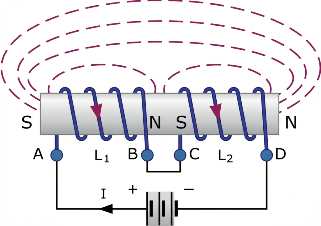
When current flows from point A to point D through two cumulatively coupled inductors, their magnetic fields reinforce each other. Therefore, the voltage equations for the two coils must account for the effect of mutual inductance.
The self-inductances of the individual coils, and , remain unchanged in the equation, while represents their mutual inductance.
The total induced EMF across the cumulatively coupled inductors is given by:
The term represents the combined effect of mutual inductance: coil influences coil , and coil influences coil .
Dividing the above equation by gives the final expression for calculating the total inductance of cumulatively coupled inductors connected in series:
Equation for Cumulatively Coupled Inductors
If one of the coils is reversed, the current still flows through both coils in series, but their magnetic fields oppose each other. In this arrangement, the mutual inductance has a subtractive effect on the total inductance, as shown below.
Differentially Coupled Inductors in Series
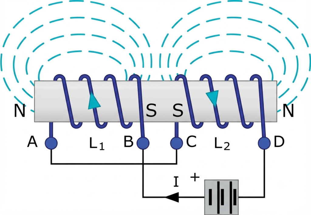
In differentially coupled inductors, the mutual EMF induced in one coil opposes its self-induced EMF because the magnetic fields produced by the two coils act in opposite directions.
To account for this opposing effect, the mutual inductance term is subtracted from the sum of the individual inductances. Therefore, the total inductance decreases, and the final equation for two differentially coupled inductors connected in series is:
Equation for Differentially Coupled Inductors
The general equation for two mutually coupled inductors connected in series depends on whether their magnetic fields reinforce or oppose each other.
Note that the factor of 2 in the term accounts for the mutual inductance acting in both directions. The current flowing through induces a voltage in , while the same current flowing through also induces a voltage in . These mutual effects either reinforce or oppose the total inductance, depending on the coils’ winding orientation and magnetic coupling.
Tutorial Worked Example No. 2
Two inductors of 15 mH each are connected in series so that their magnetic fields aid each other, producing cumulative coupling. Their mutual inductance is 4 mH. Calculate the total inductance of the series combination.
Given:
For cumulatively coupled inductors connected in series:
Substituting the values:
The total inductance is 38 mH.
Tutorial Worked Example No. 3
Two coils connected in series have self-inductances of 25 mH and 45 mH, respectively. The total inductance of the combination is 90 mH. Determine the mutual inductance between the two coils, assuming they are aiding each other.
Given:
For cumulatively coupled inductors:
Substituting the values:
The mutual inductance between the two coils is 10 mH.
Difference Between Series and Parallel Inductors
The main difference between series and parallel inductors is how they are connected in a circuit, how current and voltage are distributed, and how their equivalent inductance is calculated.
| Parameter | Inductors in Series | Inductors in Parallel |
| Definition | Inductors are connected end-to-end in a single current path. | Inductors are connected across the same two electrical nodes. |
| Total inductance | For uncoupled inductors, LT = L1 + L2 + ··· + Ln | For uncoupled inductors, 1/LT = 1/L1 + 1/L2 + ··· + 1/Ln |
| Current | The same current flows through every inductor. | The total current divides among the branches according to their inductances and circuit conditions. |
| Voltage | The total voltage equals the sum of the voltages across individual inductors. | The same voltage appears across every inductor. |
| Mutual inductance | For two coupled inductors, LT = L1 + L2 ± 2M, depending on whether the coupling is aiding or opposing. | For two coupled inductors in a specified parallel-aiding or parallel-opposing configuration, the equivalent inductance depends on the winding polarity and coupling. |
| Equivalent inductance | For uncoupled inductors, the total inductance is greater than that of any individual inductor. | For positive, uncoupled inductances, the equivalent inductance is less than the smallest individual inductance. |
| Applications | Used in filter circuits, chokes, and circuits requiring a higher inductance value. | Used in circuits requiring a lower equivalent inductance or multiple current paths. |
Note: The standard series and parallel inductance formulas assume negligible mutual coupling. When inductors are magnetically coupled, their winding orientation and mutual inductance must also be considered.
Applications of Inductors in Series
Inductors connected in series are used in various electrical and electronic circuits to control current, filter signals, store energy, and improve circuit performance. The main applications include:
1. Filtering Circuits: Series inductors are used in filter circuits to attenuate unwanted frequencies. When combined with capacitors and resistors, they help form low-pass, high-pass, and band-pass filters, depending on the circuit configuration.
2. RF Impedance Matching: In radio-frequency (RF) circuits, series inductors help match impedance between different circuit stages. Proper impedance matching improves power transfer and reduces signal reflections.
3. Energy Storage: Inductors store energy in their magnetic fields when current flows through them. This energy can be released when the current changes, making series-connected inductors useful in power supplies and energy-conversion circuits.
4. Noise Reduction: Series inductors help suppress unwanted high-frequency noise and electromagnetic interference in power supply and telecommunication circuits. They can also work with capacitors to smooth current variations and reduce ripple.
5. Tuning Circuits: Series inductors are combined with capacitors to create resonant circuits used for frequency selection. By choosing suitable inductance and capacitance values, these circuits can be tuned to specific frequencies in radio receivers, transmitters, and communication equipment.
Conclusion
When inductors are connected in series, the total inductance depends on their individual inductance values and the effect of mutual coupling. For uncoupled inductors, the total inductance is the sum of their individual inductances. However, when the magnetic fields interact, mutual inductance can increase or decrease the overall value.
Series-connected inductors are classified as cumulatively coupled (aiding) or differentially coupled (opposing). In aiding connections, mutual inductance increases the total inductance, whereas in opposing connections, it decreases the total inductance. Understanding these effects is essential for accurately calculating inductance in practical electrical and electronic circuits.
Read Next:
- AC Capacitance: Formula, Reactance & Phase Angle
- Resistors in Series: Definition, Formula, Rules, Calculation, and Examples
- Capacitors in Series and Series Capacitor Circuits – Complete Guide
- Resistors in Parallel – Parallel Connected Resistors Explained
- Voltage Divider: Rule, Equations, Formulas, and Practical Applications
- Inductor: Definition, Formula, Working Principle, Types & Applications
- Inductance of a Coil: Formula, Factors & Examples
- Mutual Inductance: Definition, Formula, Unit, Coupling Coefficient & Examples