Power diodes are a fundamental component in power electronics. These diodes can handle higher voltage and current levels, making them essential for rectification, voltage regulation, and power conversion in high-power circuits. In this comprehensive guide, we’ll dive deep into the world of power diodes, exploring their characteristics, construction, working, and much more. This article is crafted for both beginners and professionals to provide a clear understanding of power diodes and their role in modern electronics.
What is a Power Diode?
A power diode is a two-terminal semiconductor device designed to handle large currents and high voltages. Unlike small signal diodes, power diodes are built to operate in power electronics applications where high efficiency and reliability are required.
Power diodes allow current to flow in only one direction, from the anode to the cathode, just like regular diodes. However, they can withstand higher levels of electrical stress, making them suitable for converting AC to DC, voltage clamping, and overvoltage protection in high-power environments.
Symbol of Power Diode
The symbol of a power diode is similar to that of a regular diode, consisting of a triangle pointing toward a line. The triangle represents the anode, while the line represents the cathode. However, power diodes often have additional annotations, such as current and voltage ratings, to differentiate them from standard diodes.

This symbol shows the direction of conventional current flow, highlighting that the diode only conducts when the anode is more positive than the cathode.
V-I Characteristics of Power Diode
A power diode’s Voltage-Current (V-I) characteristics describe its behavior under forward and reverse bias conditions. Understanding these characteristics is essential for determining a power diode’s performance in different applications.
Forward Characteristics
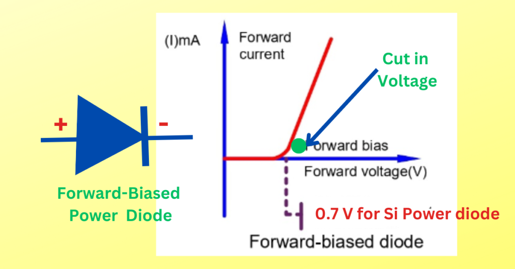
When a power diode is forward-biased (the anode is more positive than the cathode), it initially does not conduct until the applied voltage reaches a certain threshold, known as the cut-in voltage or forward voltage drop. After this point, the diode starts conducting significantly, with only a small voltage drop across it, typically between 0.7V to 1.1V depending on the type of diode.
- Forward Voltage (Vf): The voltage drops across the diode in the forward direction.
- Forward Current (If): The current flowing through the diode when forward-biased.
The forward voltage drop remains relatively constant with increasing forward current, ensuring low power loss and high efficiency.
Reverse Characteristics
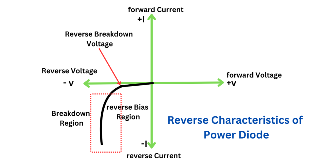
When a power diode is reverse-biased (the cathode is more positive than the anode), it ideally blocks any current flow, acting as an open circuit. However, a small leakage current, known as the reverse leakage current, flows due to minority carriers. This current is typically very small and can be ignored in most cases.
- Reverse Breakdown Voltage (Vbr): The voltage at which the diode starts conducting in the reverse direction, potentially causing damage.
Exceeding the reverse breakdown voltage can lead to permanent damage, making it crucial to choose diodes with suitable reverse voltage ratings for high-voltage applications.
V-I Characteristics Graph
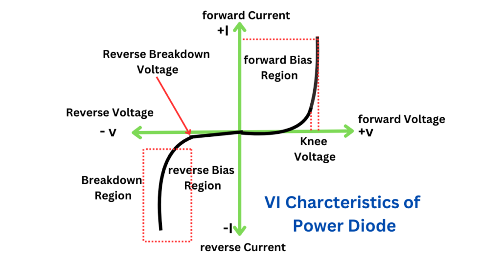
The V-I characteristics graph of a power diode has three key regions:
- Forward Conduction Region: The diode conducts with a minimal voltage drop.
- Reverse Blocking Region: The diode blocks the current until the reverse breakdown voltage.
- Reverse Breakdown Region: The diode conducts in the reverse direction, which can cause permanent damage.
This characteristic curve helps engineers understand how a power diode behaves under different operating conditions.
Reverse Recovery Characteristics
Reverse recovery characteristics are an essential parameter in power diodes. When a power diode switches from the conducting (forward-biased) state to the blocking (reverse-biased) state, it takes a brief period for the current to drop to zero. This period is known as the reverse recovery time (trr).
During the reverse recovery time, the diode may conduct in the reverse direction due to the stored charge carriers. This can lead to power loss and electromagnetic interference (EMI) in high-frequency applications.
Factors Affecting Reverse Recovery Time
- Charge Storage: The amount of charge stored in the depletion region.
- Doping Levels: Higher doping levels result in faster recovery times but can increase forward voltage drop.
- Temperature: Higher temperatures can increase reverse recovery time.
Shorter reverse recovery times are desirable for high-frequency switching applications, as they reduce power loss and improve efficiency.
Need for Power Diode
Power diodes are indispensable in power electronics because of their ability to handle large currents and voltages. Here’s why power diodes are needed:
- High Power Handling Capability: Power diodes can handle high currents and voltages, making them ideal for power rectification and voltage regulation.
- Efficient Power Conversion: With a low forward voltage drop and minimal power loss, power diodes ensure efficient power conversion in high-power circuits.
- Robustness and Reliability: Power diodes are designed to operate in harsh environments, ensuring long-term reliability in industrial and automotive applications.
Construction of Power Diodes
The construction of a power diode differs significantly from that of a standard signal diode. A power diode is typically made using silicon due to its stability, high thermal conductivity, and ease of manufacturing. It consists of the following regions:
- Heavily Doped n+ Region (Cathode): This region is highly conductive and ensures low resistance, allowing efficient conduction of large currents.
- Lightly Doped n- Region (Drift Region): The lightly doped drift region is crucial for withstanding high voltage levels without breaking down.
- Heavily Doped p+ Region (Anode): The p+ region forms the p-n junction with the n-region, allowing control over current flow.
The thickness of the drift region determines the diode’s breakdown voltage, while the heavily doped regions minimize the forward voltage drop.
Materials Used in Power Diodes
- Silicon (Si): Most power diodes are made using silicon due to its excellent electrical properties.
- Gallium Arsenide (GaAs): Used in high-speed applications due to its high electron mobility.
- Silicon Carbide (SiC): Offers high thermal conductivity and can operate at higher temperatures.
The choice of material depends on the specific requirements of the application, such as speed, temperature, and power handling capabilities.
Working of Power Diodes
Power diodes are crucial components in various high-power applications such as rectification, freewheeling in motor drives, and protection circuits. Their working principle is based on the PN junction semiconductor technology, which allows current to flow in only one direction (from the anode to the cathode) and blocks it in the reverse direction.
Here’s a detailed breakdown of the working of power diodes:
1. Forward Bias Condition (Conducting State)
- When the anode is connected to a positive voltage relative to the cathode (forward-biased), the depletion region at the PN junction narrows.
- Once the forward voltage exceeds a certain threshold (typically 0.7V for silicon diodes or 0.3V for Schottky diodes), the diode starts conducting current.
- Current Flow: Electrons from the N-region move toward the P-region, and holes from the P-region move toward the N-region. This movement results in current flow from the anode to the cathode.
- Forward Voltage Drop: Even when the diode conducts, there is a small voltage drop across the diode, known as the forward voltage drop (VF). This is usually between 0.7V and 1.2V for standard power diodes.
2. Reverse Bias Condition (Blocking State)
- When the anode is connected to a negative voltage relative to the cathode (reverse-biased), the depletion region at the PN junction widens, and no significant current flows through the diode.
- Reverse Current: A very small leakage current called reverse leakage current (IR), can flow due to minority carriers. This current is usually negligible in standard conditions.
- Reverse Breakdown: If the reverse voltage exceeds the diode’s reverse breakdown voltage (VR), the depletion region can no longer block the current, and the diode will begin to conduct heavily in the reverse direction, which can damage the diode if not designed for breakdown operation (like a Zener diode).
Key Points in Power Diode Operation
- Forward Bias: The diode conducts when the anode is positive relative to the cathode.
- Reverse Bias: The diode blocks current flow when the cathode is positive relative to the anode.
- Breakdown Voltage: The maximum reverse voltage that the diode can withstand without conducting in reverse.
Types of Power Diodes
Power diodes are categorized based on their construction and application:
- Standard Power Diodes:
- Used in low-speed applications like power supplies and rectifiers.
- Long reverse recovery time makes them unsuitable for high-frequency circuits.
- Fast Recovery Diodes:
- Designed for high-frequency applications with shorter reverse recovery times.
- Ideal for use in inverters and switching power supplies.
- Schottky Diodes:
- Known for their low forward voltage drop and fast switching characteristics.
- Commonly used in high-efficiency circuits and low-voltage applications.
- Ultrafast Recovery Diodes:
- Shorter reverse recovery time than fast recovery diodes.
- Suitable for very high-speed switching applications.
- Soft Recovery Diodes:
- Controlled reverse recovery time minimizes EMI in switching circuits.
- Often used in power factor correction (PFC) and rectifier circuits.
Comparison of Different Types of Power Diodes
| Type | Recovery Time | Voltage Drop | Application |
|---|---|---|---|
| Standard Power Diode | Long | High | Low-speed rectification |
| Fast Recovery Diode | Short | Moderate | Inverters, switching supplies |
| Schottky Diode | Very Short | Low | Low-voltage, high-efficiency |
| Ultrafast Recovery Diode | Very Short | Low | High-speed switching |
| Soft Recovery Diode | Controlled | Moderate | EMI-sensitive circuits |
Applications of Power Diodes
Power diodes are used in a variety of high-power applications:
- Rectification: Converting AC to DC in power supplies.
- Voltage Clamping: Protecting circuits from overvoltage conditions.
- Voltage Regulation: Maintaining a constant voltage level.
- Freewheeling Diodes: Allowing current to circulate in inductive loads, such as motors, when the main switch is off.
- Inverters and Converters: Ensuring efficient power conversion in solar and wind energy systems.
- Snubber Circuits: Reducing voltage spikes and protecting components in high-power circuits.
Selection of Power Diodes
When selecting power diodes for specific applications, several factors must be considered to ensure the diode operates effectively, efficiently, and safely. Here is a guide on how to select power diodes based on key parameters:
1. Maximum Forward Current (IF)
- Rated Current Capacity: The diode must be able to handle the maximum continuous current that will flow through it. The forward current rating is often specified as IF(AV) or IF(RMS), which refers to the average or RMS forward current.
- Consider Safety Margin: It’s a good practice to select a diode with a current rating higher than the expected operating current, typically with a margin of 20-30%.
2. Reverse Voltage Rating (VRRM or VBR)
- Maximum Reverse Voltage: The diode’s reverse voltage rating (VRRM) must exceed the maximum voltage the diode will encounter when reverse-biased. This prevents the breakdown of the diode.
- For AC rectification, the reverse voltage should generally be 1.5 to 2 times the peak AC voltage to account for surges.
3. Power Dissipation (Pmax)
- Thermal Considerations: Power diodes dissipate energy as heat, which is determined by the forward voltage drop and the current passing through them. Ensure the diode can handle the power dissipation without exceeding its temperature rating.
- Use heat sinks or other thermal management techniques if necessary, especially for high-power applications.
4. Forward Voltage Drop (VF)
- Efficiency Considerations: The forward voltage drop (VF) across the diode impacts the overall power efficiency of the circuit. Lower forward voltage drop diodes are preferred in applications where energy efficiency is critical, such as in power supplies and converters.
5. Switching Speed
- Reverse Recovery Time (trr): In high-frequency switching applications, such as SMPS (Switched-Mode Power Supplies) or motor drives, the switching speed of the diode becomes critical. Choose fast recovery diodes or Schottky diodes for high-speed applications as they have very low reverse recovery time.
- For low-frequency or DC applications, standard power diodes (like silicon rectifiers) can be used.
6. Junction Temperature (Tj)
- Temperature Tolerance: Ensure the diode’s junction temperature rating is suitable for the operating environment. Power diodes often have a maximum junction temperature rating of around 150°C to 200°C. Thermal derating should be considered if the diode operates in hot environments or with high power dissipation.
7. Types of Power Diodes
- Standard Diodes: For general-purpose rectification with lower switching frequencies.
- Fast Recovery Diodes: For applications requiring faster switching times, such as SMPS and inverters.
- Schottky Diodes: Offer very low forward voltage drop and fast switching speeds, making them ideal for high-efficiency applications. However, they are usually rated for lower reverse voltages compared to standard silicon diodes.
- Zener Diodes: Used when voltage regulation or over-voltage protection is needed.
8. Package Type
- Package Selection: The physical package (TO-220, DO-201, SMD, etc.) should match your thermal and mounting requirements. Ensure that the chosen package allows for adequate heat dissipation or is compatible with cooling solutions like heat sinks.
9. Surge Current Rating (IFSM)
- Inrush Current: In some applications, such as rectifiers, the diode may experience large inrush or surge currents for short periods. The surge current rating (IFSM) should be greater than the highest inrush current the diode will encounter.
- For example, during power-on or when capacitors charge, the initial current may be many times higher than the normal operating current.
10. Reverse Leakage Current (IR)
- Leakage Considerations: This is the small current that flows when the diode is reverse-biased. While usually small, excessive reverse leakage current can lead to higher losses, especially in high-temperature environments or sensitive circuits.
11. Application-Specific Considerations
- Rectification: For rectifiers, the current handling and reverse voltage ratings are the primary considerations.
- Switching Applications: For high-frequency switching, fast recovery or Schottky diodes are more suitable due to lower reverse recovery times.
- Power Supply or Voltage Clamping: Zener or Schottky diodes may be selected for voltage clamping or regulation.
Example of Power Diode Selection for an Application:
Suppose you’re designing a rectifier circuit for a 24V DC power supply:
- Maximum Input Voltage: 24V AC with a peak voltage of about 34V (considering √2 factors).
- Diode Selection:
- Reverse voltage rating of around 70V or higher (double the peak AC voltage).
- Average forward current of 5A, so you may select a diode rated for 10A to handle surge and heat dissipation.
- Forward voltage drop should be low, preferably under 1V, to minimize power losses.
- For switching circuits, a fast recovery or Schottky diode would be preferable to minimize switching losses.
Related Articles: