Introduction
In the study of semiconductor diodes, the term “knee voltage,” also known as the “cut-in voltage” or “threshold voltage,” plays a crucial role in understanding diode behavior. This concept is pivotal for both theoretical analysis and practical applications in electronics. This article explores the definition of knee voltage, provides a detailed explanation, and analyzes its representation in the voltage-current (VI) characteristics curve of a diode.
Definition of Knee Voltage
Knee voltage is the minimum forward bias voltage at which a diode starts to conduct a significant amount of current. Below this voltage, the diode remains in a non-conductive state, effectively acting as an open circuit. The knee voltage varies depending on the material and construction of the diode, typically 0.3 and 0.7 volts for germanium and silicon diode, respectively,
Explanation of Knee Voltage
The knee voltage is intrinsic to the physical properties of the semiconductor material used in the diode. It represents the energy required to overcome the potential barrier at the PN junction—a boundary that separates the p-type and n-type semiconductor materials within the diode.
When a diode is forward-biased (positive voltage at the anode and negative at the cathode), the external voltage applied to the diode reduces the width of the depletion region at the PN junction. Once the applied voltage exceeds the cut-in voltage or cut-in voltage, it sufficiently narrows the depletion zone, allowing charge carriers (electrons and holes) to cross the junction easily. This transition facilitates a significant increase in current, marking the diode’s shift from its off state (high resistance) to an on state (low resistance).
VI Curve and Knee Voltage
The VI curve of a diode is a graphical representation of the relationship between the applied voltage (horizontal axis) and the resulting current (vertical axis).
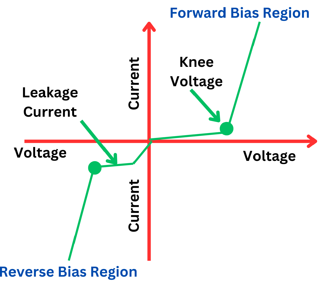
The curve typically features three distinct regions:
- Reverse Bias Region: The left portion of the graph where the diode blocks current, showing minimal current flow despite the increase in reverse voltage.
- Forward Bias Region Before the Knee: This region shows a gradual increase in current with increasing voltage, but the current remains relatively low.
- Forward Bias Region After the Knee: Immediately following the knee point, the curve steepens dramatically, indicating a sharp increase in current flow as the diode enters its conductive state.
The knee point on the curve is critical because it indicates the voltage at which the diode effectively starts to allow significant current flow, transitioning from its blocking state. This point is crucial for designers of electronic circuits, as it impacts how diodes are implemented in various applications, from voltage regulators to rectifiers.
Conclusion
Knee voltage is a fundamental concept in diode electronics, representing the critical threshold at which a diode begins to conduct electricity significantly. Understanding this parameter is essential for effectively utilizing diodes in electronic circuits, ensuring that they operate within desired parameters. The knee voltage not only informs about the operational starting point of a diode but also assists in selecting the right diode based on its material properties and expected performance in specific applications. Through detailed analysis of the VI curve, electronics professionals and enthusiasts can gain deeper insights into the behavior of diodes under different voltage conditions, enhancing the design and functionality of electronic devices.