1). What is a Power Amplifier?
A power amplifier amplifies a weak signal and increases its power to a level sufficient to drive an output device, such as a loudspeaker. A power amplifier boosts the signal’s amplitude while maintaining its original characteristics, and bridges the gap between low-power signal sources and high-power output devices.
2). What are the Characteristics of a Power Amplifier?
- The primary function of a power amplifier is to deliver high-output power to drive devices such as loudspeakers or other load equipment effectively.
- A power amplifier should maintain the linearity of the input signal, meaning the output should be an amplified replica of the input without introducing distortion.
- Gain is the ratio of the output signal power to the input signal power. Power amplifiers typically have a high gain to amplify weak signals to the required power levels.
- A good power amplifier provides a consistent amplification across the desired frequency range, ensuring fidelity to the input signal.
- Power amplifiers are designed to match the impedance of the load device (e.g., speakers) for efficient power transfer.
- Low distortion is crucial in power amplifiers to avoid alterations in the waveform of the output signal. Common types include harmonic distortion and intermodulation distortion.
- The amplifier should remain stable under varying load conditions, temperature changes, or other environmental factors to prevent oscillations or malfunctions.
- Power amplifiers generate significant heat during operation, so efficient heat dissipation mechanisms like heatsinks or cooling fans are essential.
- Power amplifiers are classified into different classes (Class A, B, AB, D, etc.), each with unique characteristics related to efficiency, distortion, and application.
- A power amplifier must handle varying load impedances without performance degradation or damage to the system.
- A high signal-to-noise ratio SNR ensures that the output signal remains clear and free from noise or interference introduced by the amplifier.
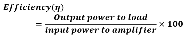
3). Define Power Amplifier Efficiency
Power Amplifier Efficiency is the ratio of the useful output power delivered to the load (such as a speaker) to the total power drawn from the power supply, expressed as a percentage. It indicates how effectively the amplifier converts input electrical power into output power for driving the load.
4). What is meant by Amplifier Class?
The class of an amplifier refers to the method or mode in which the amplifier operates to process and amplify the input signal. It primarily determines the relationship between the input signal, the output signal, and the amplifier’s efficiency, linearity, and distortion characteristics.
5). What is a Class A power amplifier?
A Class A power amplifier is a type of amplifier in which the output current flows through the active device (transistor or vacuum tube) for the entire 360° of the input signal cycle. This means the amplifier remains in an “on” state throughout the entire signal cycle, amplifying both the positive and negative halves of the waveform without interruption.
6). What are the advantages and disadvantages of a class A power amplifier?
Advantages
- High linearity.
- Low distortion.
- Simple circuit design.
- Suitable for high-fidelity applications.
- Amplifies the entire input signal without interruption.
Disadvantages
- Poor efficiency (20-30%).
- High power consumption.
- Significant heat generation.
- Requires large heat sinks or cooling systems.
- Not ideal for high-power applications.
7). What is a Power MOSFET?
A Power MOSFET (Metal-Oxide-Semiconductor Field-Effect Transistor) is a type of MOSFET specifically designed to handle high power levels in electronic circuits. It is widely used in applications requiring high switching speed and efficiency, such as power converters, motor drives, and power amplifiers.
Power MOSFETs are commonly used in power devices due to the following features:
- Low gate drive power requirements.
- High switching speeds.
- Capability for parallel operation.
8). What are the different types of Distortion
- Amplitude Distortion
- Frequency Distortion
- Phase Distortion
- Harmonic Distortion
- Intermodulation Distortion
- Crossover Distortion
- Clipping Distortion
- Transient Distortion
- Envelope Distortion
- Nonlinear Distortion
9). Define Velocity Saturation
Velocity saturation is a phenomenon in semiconductor physics where the drift velocity of charge carriers (such as electrons or holes) reaches a maximum limit, regardless of further increases in the applied electric field. Beyond this point, increasing the electric field does not significantly increase the carrier velocity due to scattering effects.
10). What is a DC-DC Converter?
A DC-DC converter is an electronic device or circuit that converts a direct current (DC) voltage level from one value to another. It is widely used in power electronics to efficiently transfer energy between different voltage levels. It is also called a DC Chopper.
11). What are the applications for DC Choppers?
- DC choppers are extensively used in electric vehicles, trolley cars, marine hoists, trucks, and mine haulers. They provide smooth acceleration control, high efficiency, and fast response, ensuring optimal performance.
- DC choppers enable regenerative braking in motors, allowing energy to be fed back into the power supply. This results in significant energy savings, especially in transportation systems with frequent stops, such as trains and buses.
- They are used as DC voltage regulators to ensure stable and adjustable voltage levels for various applications, enhancing the efficiency of power systems.
12). Define a Buck Converter
Buck converters, also known as step-down converters, are designed to provide an output voltage that is lower than the input voltage.
The average output voltage is always reduced compared to the input voltage.
13). What are the uses of the Buck Converter?
- Powering low-voltage devices from a higher voltage source.
- Voltage regulation in battery-powered systems.
- Supplying microprocessors and digital circuits.
- Renewable energy systems (solar power management).
- LED drivers for consistent brightness.
- Automotive applications for voltage step-down.
- Industrial equipment with DC power control.
14). Define Boost Converter
A boost converter is a DC-DC power converter that steps up (increases) the input voltage to a higher output voltage while maintaining power conservation. It operates by storing energy in an inductor during the “on” state of a switch (typically a transistor) and releasing it to the load at a higher voltage during the “off” state. Boost converters are widely used in applications requiring voltage levels higher than the available source voltage.
15). What is a Buck-Boost Converter?
A buck-boost converter is a type of DC-DC converter capable of stepping up or stepping down the input voltage to produce a desired output voltage. It combines the functionalities of both buck (step-down) and boost (step-up) converters in a single circuit.
Depending on the input voltage relative to the desired output, the converter operates either in buck mode (lowering voltage) or boost mode (raising voltage). The output voltage can be higher, lower, or even inverted relative to the input voltage, depending on the design.
16). Write advantages of Converter
- High efficiency in power conversion.
- Compact and lightweight design.
- Precise voltage and current regulation.
- Ability to step up, step down, or invert voltage.
- Wide range of applications (industrial, automotive, renewable energy).
- Reduced energy losses compared to linear regulators.
- Enhanced device performance and battery life.
17). Why do we need a Power Amplifier?
- To increase the amplitude of weak signals for driving speakers or other output devices.
- To boost the signal power for long-distance transmission in communication systems.
- To ensure sufficient power for driving high-power loads like motors, actuators, or antennas.
- To improve the quality of the output signal, maintaining signal integrity at higher power levels.
- To enable audio systems, radios, and other devices to produce loud and clear sound or signal transmission.
18). Define Cross-Over Distortion
Cross-Over Distortion is a type of distortion that occurs in push-pull amplifier circuits, typically in class B or AB amplifiers. It arises when the output signal transitions between the two active devices (transistors or MOSFETs) that are amplifying the positive and negative halves of the waveform.
At the point where the output switches from one device to the other, there is a brief period during which neither device is fully conducting, leading to a non-linear transition. This results in a noticeable distortion, especially at low signal levels, where the waveform is not smoothly transferred between the devices.
At the zero-crossing points, neither transistor Q1 nor Q2 conducts, causing a gap between the positive and negative halves of the output signals. This results in a discontinuity in the output waveform, known as cross-over distortion.
Cross-over distortion can degrade the quality of audio output in amplifiers.
19). What is the Circuit Turn-Off Time?
Circuit Turn-Off Time refers to the duration required for a circuit, typically a transistor or switching device, to transition from the “on” state to the “off” state after the control signal is removed or turned off. During this time, the device stops conducting current, and the output voltage or current reaches a steady state.
20). Why should circuit turn-off time be longer than thyristor turn-off time?
The circuit turn-off time must be longer than the thyristor turn-off time to ensure that the thyristor is fully turned off and does not accidentally turn on again due to any residual current or voltage. If the circuit’s turn-off time is too short, the thyristor may not completely cease conducting, leading to unwanted conduction or a “false triggering.”
A longer turn-off time ensures that:
- The thyristor remains in the off state without any unintended re-triggering.
- The circuit fully dissipates any stored charge in the thyristor, preventing latch-up or malfunction.
- The system operates reliably, with proper control over power flow, especially in high-power applications.
21). What is meant by a Phase Controlled Rectifier?
A Phase Controlled Rectifier (PCR) is a type of rectifier where the output voltage is controlled by adjusting the phase angle of the input AC signal. It typically uses thyristors (SCRs) to rectify the AC input, and the firing angle (or phase angle) of the thyristor determines when the device starts conducting within the AC cycle.
By delaying the triggering of the thyristors, the rectifier controls the portion of the AC waveform that is passed to the output. This allows for variable DC output voltage, making phase-controlled rectifiers ideal for applications that require precise control over power, such as in motor drives and controlled power supplies.
22). What is meant by Delay Angle?
The delay angle (often referred to as the firing angle) is the angle in the AC cycle at which a controlled rectifier (such as a Phase Controlled Rectifier) begins conducting. It is the time delay between the zero crossing of the input AC voltage and the point at which the rectifier (typically a thyristor) is triggered to conduct.
23). What is the Commutation Angle (or) Overlap Angle?
The commutation angle (also known as the overlap angle) refers to the period in an AC cycle when two thyristors (or other semiconductor devices) in a phase-controlled rectifier are momentarily conducting simultaneously. This occurs during the transition from one thyristor turning off and the next one turning on, creating a brief overlap
24). What is the Displacement Factor?
The displacement factor is a measure of the phase difference between the fundamental components of the current and voltage waveforms in an AC circuit. It is defined as the cosine of the phase angle (θ) between the fundamental voltage and current waveforms. For linear loads with sinusoidal voltages and currents, the displacement factor is equal to the power factor.
A displacement factor of 1 indicates that the current and voltage are perfectly in phase (i.e., purely resistive load), while a value less than 1 indicates a phase shift, which is common in inductive or capacitive loads.
25). What is meant by Step-Up and Step-Down Chopper?
A step-up chopper is a type of DC-DC converter that increases the input voltage to a higher output voltage. It operates by storing energy in an inductor during the “on” state of the switch and releasing it at a higher voltage during the “off” state. This type of chopper is also known as a boost converter.
A step-down chopper is a DC-DC converter that reduces the input voltage to a lower output voltage. It works by transferring energy through an inductor, capacitor, and switching components, effectively lowering the output voltage while maintaining power efficiency. This type of chopper is commonly known as a buck converter.
26). What is holding current in SCR?
The holding current is the minimum current required to keep an SCR (Silicon Controlled Rectifier) conducting after it has been triggered into the “on” state. Once the SCR is turned on (fired) by a gate signal, it continues conducting as long as the current through it stays above this holding current level.
If the current falls below the holding current, the SCR will turn off, even if it is still forward-biased. In other words, the SCR will not remain conducting unless the current through it is sufficiently high to maintain its conduction state.
27). What is the latching current in SCR?
The latching current is the minimum current required to turn on an SCR (Silicon Controlled Rectifier) and latch it into the “on” state (conduction state) once it is triggered. When the SCR is forward biased and a gate signal is applied, it will begin conducting if the current through it is above this threshold value.
- If the current through the SCR exceeds the latching current, the SCR will remain in the “on” state even after the gate signal is removed.
- Once the SCR is latched, it continues to conduct until the current falls below the holding current or the device is forced into a non-conducting state by an external circuit.
28). What are the different turn-on methods of SCR?
- Forward voltage triggering
- Gate Triggering
- dv/dt triggering
- Temperature triggering
- Light triggering
29). What is snubber circuit?
The snubber circuit is used to protect the SCR from dv/dt (rate of change of voltage) stress. It consists of a resistor and capacitor connected in series and is placed in parallel with the SCR.
The primary purpose of a snubber circuit is to dampen high-frequency oscillations and limit voltage transients that could damage sensitive components like SCRs, transistors, or diodes.
30). What are the types of snubber circuits?
- Series RC Snubber: Typically used across the switching device (e.g., transistor or SCR) to suppress spikes.
- Parallel RC Snubber: Used across inductive components to filter out high-frequency noise.
- Active Snubber: Uses active components like transistors or operational amplifiers to control the transient response.
31). What is hard switching of the thyristor?
Hard switching of a thyristor refers to the process of turning the device on or off when there is a significant voltage or current change at the moment of switching. In hard switching, the thyristor is subjected to a sudden and high rate of voltage or current, which can cause significant stress on the device and lead to issues like electromagnetic interference (EMI), switching losses, and damage due to voltage spikes.
When the gate current is much higher than the required value, the SCR is considered to be hard fired. This reduces the turn-on time and improves the di/dt capability.
32). What is meant by SOA?
The Safe Operating Area (SOA) defines the voltage and current limits within which a power device can operate without risk of destructive failure.
33). Name the main components used for isolating the Power Circuits and power semiconductors from the low-power circuit
- Optocouplers (Optoisolators)
- Transformers
- Relays
- Isolation Amplifiers
- Isolation Diodes
34). Name some of the current controlled (current driven) devices
- SCR (Silicon Controlled Rectifier)
- SCS (Silicon Controlled Switch)
- GTO (Gate Turn-Off Thyristor)
35). Name some of the voltage-driven ( Voltage controlled) devices
- IGBT – Insulated Gate Bipolar Transistor
- MCT – Metal–Oxide–Semiconductor Controlled Thyristor
- IGCT – Integrated Gate Commutated Thyristor
- SIT – Static Induction Transistor
36). What is the duty cycle?
It is the ratio of the ON time of the chopper to the total time period of the chopper.
D = Ton / (Ton + Toff)
37). Can a fuse with an AC voltage rating be used in DC applications?
A fuse with an AC voltage rating should not be used in DC applications unless it specifically mentions compatibility with DC voltage. Here’s why:
- Breaking Capacity: In DC circuits, the current does not cross zero (as it does in AC), making it harder for the fuse to extinguish the arc once it is blown. AC fuses are designed to handle the current zero-crossing point, which helps to quench the arc more easily. DC circuits require fuses with a higher breaking capacity because of the continuous current flow.
- Voltage Rating: The voltage rating of a fuse is related to its ability to withstand the voltage when the fuse blows. AC voltage ratings are generally lower for the same fuse size because of the nature of AC’s alternating current, which helps with arc extinguishing. Using an AC-rated fuse in a DC circuit can result in unsafe operation or failure.
Therefore, it’s crucial to use a DC-rated fuse in DC applications, as it is specifically designed to handle the unique challenges of DC circuits, including higher arc-quenching capabilities and a higher voltage rating.
38.) What are the characteristics of an ideal Opamp?
- Infinite Open-Loop Gain
- Infinite Input Impedance
- Zero Output Impedance
- Infinite Bandwidth
- Zero Offset Voltage
- Infinite Common-Mode Rejection Ratio (CMRR)
- Power Supply Rejection Ratio (PSRR)
- Zero Input Bias Current
- Zero Noise
39). For High voltage applications will you prefer MOSFET or IGBT?
- For high-voltage applications, IGBTs should be used.
- MOSFETs are low-voltage devices, with a lower voltage rating compared to IGBTs.
- General rule: MOSFETs are suitable for applications with a breakdown voltage of less than 250V.
- IGBTs are suitable for applications with a breakdown voltage of up to 1000V.
40). For High frequency applications will you prefer MOSFET or IGBT? Why?
- For high-frequency applications, MOSFET is the preferred device.
- MOSFETs have lower switching losses compared to IGBTs, making them more suitable for high-frequency operations.
- General guideline: For low-frequency applications (up to 20 kHz), IGBTs are typically used.
- For high-frequency applications (above 200 kHz), MOSFETs are the better choice.
41). To design the buck converter, what are basic & essential information (parameters) we need to get from the Customer?
We require the following inputs from the customer:
- Output Voltage (VOUT)
- Input Voltage (VIN)
- Output Current (IOUT)
- Maximum allowed ripple voltage at the output
- Efficiency of the converter
42). How to select the inductor for the buck converter?
We can start with the basic equation for the voltage across an inductor:
- Voltage across Inductor (VL) = L * di/dt
Rewriting this equation:
- L = VL * dt / di
Where:
- VL is the maximum voltage that appears across the inductor.
- dt is the time during which the maximum voltage appears across the inductor.
- di is the ripple current.
Explanation:
- VL: The maximum voltage across the inductor when the power switch is turned on. During this time, the voltage will be:
- VL = VOUT – VIN
- dt: The time duration when the maximum voltage appears across the inductor, which is:
- dt = D / FS, where D is the duty cycle, and FS is the switching frequency.
- di: The ripple current, which is typically assumed to be between 10% to 30% of the load current.
By knowing these values, we can calculate the required inductance value for the buck converter.
43). What are the various parameters to consider when selecting IGBT?
In an IGBT datasheet, the following parameters should be focused on:
- Collector-to-Emitter Voltage (VCES)
- Collector Current (IC)
- Collector Power Dissipation (PC)
- Junction Temperature (Tj)
44). For Selecting MOSFET, what are the major parameters to consider in the datasheet?
- Drain-to-Source Voltage (VDS)
- Continuous Drain Current (ID)
- Gate Threshold Voltage (VGS(th))
- RDS(on) (On-Resistance)
- Total Gate Charge (Qg)
- Gate-Source Voltage (VGS)
- Power Dissipation (PD)
- Drain-to-Source Breakdown Voltage (Vds(max))
- Thermal Resistance (RthJC, RthJA)
- Maximum Junction Temperature (Tj)
- Body Diode Forward Voltage (Vf)
- Switching Speed (Rise and Fall Time)
45). What are the advantages of a free-wheeling diode in a rectifier circuit?
- Prevents voltage spikes
- Reduces current surge
- Improves efficiency
- Protects semiconductor devices
- Ensures continuous current flow
- Reduces switching losses
- Enhances reliability
- Minimizes harmonic distortion
46). What is meant by commutation?
The process of reversing the direction of current flow in a specific path of the circuit, it is typically used to turn off the SCR.
47). What are the types of commutation?
- Natural commutation
- Forced commutation
48). What is natural commutation?
Natural commutation is the process where the current flowing through the thyristor naturally reaches zero, allowing the thyristor to turn off.
49). What is forced commutation?
Forced commutation is the process where external circuitry forces the current flowing through the thyristor to become zero, turning it off.
50). What are the types of commutation with respect to the commutation process?
- Voltage commutated chopper
- Current commutated chopper
- Load commutated chopper
51). What is meant by cyclo-converter?
It is also referred to as a frequency changer, as it converts input power at one frequency to output power at a different frequency in a single stage of conversion.
52). What are the types of cyclo-converters?
- Step up cyclo-converter
- Step down cyclo-converter
53). What is a step-down cyclo-converter?
A step-down cyclo-converter is a type of frequency converter that directly converts AC power from one frequency to another, typically with a lower output frequency. It steps down the input frequency (usually higher) to a lower output frequency, while maintaining the same voltage or reducing it depending on the design. Cyclo-converters operate by switching the input AC waveform in a controlled manner, using power electronic devices like thyristors or triacs, to achieve the desired frequency conversion without the need for an intermediate DC stage.
54). What is a step-up cyclo-converter?
A step-up cyclo-converter is a type of frequency converter that converts AC power from a lower input frequency to a higher output frequency in a single stage. It increases the frequency of the input AC signal while maintaining or adjusting the voltage level as required. Step-up cyclo-converters operate by switching the input waveform in a controlled manner using power electronic devices like thyristors or triacs, allowing the conversion without an intermediate DC stage. These converters are typically used in applications where high-frequency AC signals are needed from a low-frequency power source.
55). What does the Voltmeter in AC mode show? Is it RMS value or the peak value?
In AC mode, a multimeter displays the RMS value of the voltage or current. In DC mode, it also shows the RMS value.
56). What are the control strategies of the chopper?
The control strategies of a chopper are:
- Pulse Width Modulation (PWM) – Variable TON, constant frequency
- Frequency Modulation – Constant TON or TOFF, variable frequency
- Current Limit Control (CLC)
57). Give some examples of power electronics applications in day-to-day life.
There are numerous power electronics applications. Some common ones that we encounter in daily life include:
- UPS – Uninterruptible Power Supply
- SMPS – Switch Mode Power Supply
- Speed Control of Motors
- ICU (Intensive Care Unit) Equipment
- Electric Vehicles (EVs)
- Solar Power Systems
- Electric Heating Systems
- HVDC (High Voltage Direct Current) Transmission
- Induction Heating
- Battery Chargers
- Welding Machines
- Lighting Control Systems
58). Why are the IGBTs very popular nowadays?
- High Voltage Capability: Can handle high voltages (up to 3 kV or more).
- High Current Capacity: Suitable for high current applications.
- Low Switching Losses: Faster switching with minimal losses compared to traditional devices.
- Efficiency: Offers higher efficiency in power conversion and control.
- Versatility: Suitable for both AC and DC applications.
- Better Thermal Performance: Can operate at higher temperatures than other power devices.
- Easy to Drive: Requires low gate drive power compared to other power devices like MOSFETs.
- Wide Application Range: Used in industrial, automotive, and renewable energy sectors.
- Cost-Effective: Offers a balance of performance and cost for medium to high power applications.
59). Why IGBT is a voltage-controlled device?
IGBT (Insulated Gate Bipolar Transistor) is considered a voltage-controlled device because its operation is controlled by the voltage applied to the gate terminal. The gate voltage determines whether the IGBT is in the on (saturated) or off (cutoff) state.
60). Why Power MOSFET is a voltage-controlled device?
Power MOSFET (Metal-Oxide-Semiconductor Field-Effect Transistor) is a voltage-controlled device because its operation is governed by the voltage applied to its gate terminal, not by the current.
61). Why Power BJT is a current-controlled device?
The Power BJT (Bipolar Junction Transistor) is a current-controlled device because its operation is primarily controlled by the current applied to its base terminal, rather than the voltage.
62). What are the different types of power MOSFET?
The different types of power MOSFETs are:
- Enhancement-mode MOSFET (E-MOSFET):
- Depletion-mode MOSFET (D-MOSFET):
- N-channel MOSFET
- P-channel MOSFET
- Dual-gate MOSFET
- Trench MOSFET
- Super Junction MOSFET (SJ-MOSFET)
- V-Groove MOSFET
63). How can a thyristor turned off?
A thyristor can be turned off by reducing the anode current below the latching current. The latching current is the minimum current required to keep the thyristor in the on state. If the current falls below this threshold, the thyristor will turn off.
64). What is the turn-off time for converter-grade SCRs and inverter-grade SCRs?
The turn-off time for converter-grade SCRs is between 50 to 100 ms, while for inverter-grade SCRs, it ranges from 3 to 50 ms.
65). What are the advantages of GTO over SCR?
The advantages of GTO (Gate Turn-Off Thyristor) over SCR (Silicon Controlled Rectifier) are:
- Gate Turn-Off Capability: Unlike SCRs, GTOs can be turned off by applying a negative gate current, eliminating the need for external circuits to forcefully turn off the device.
- Faster Switching: GTOs offer faster switching times compared to SCRs, which improves efficiency in high-frequency applications.
- No Need for Commutation Circuits: GTOs can turn off by the gate signal itself, whereas SCRs require external commutation circuits to force them off.
- Better Control: The gate control in GTOs allows for more precise control over the device, enabling better modulation and operation in applications like inverters and choppers.
- Higher Efficiency: Due to their ability to turn off without external intervention, GTOs reduce losses and improve the overall efficiency of power electronics systems.
- Reduced Complexity: Since GTOs do not require external commutation circuits, they simplify the design and reduce the complexity of power control systems.
66). What is meant by a phase-controlled rectifier?
A phase-controlled rectifier is a type of rectifier where the output DC voltage is controlled by adjusting the phase angle of the input AC signal. This is typically achieved by using a thyristor (or SCR) which can be triggered at specific points in the AC cycle.
67). What is meant by input power factor in a controlled rectifier?
The input power factor is defined as the ratio of the total mean input power to the total RMS input volt-amperes.
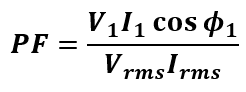
Where:
- V1 = Phase Voltage
- I1 = Fundamental component of the supply current
- ϕ1 = Input displacement angle
- Irms = Supply RMS current
68). Give an expression for the average voltage of single phase semiconverters.
Average output voltage Vdc = (Vm / π) (1 + cos α ).
69). What are the advantages of a six-pulse converter?
- Simple Design
- Good Efficiency
- Improved Power Factor
- Wide Application Range
- Reduced Harmonic Distortion
70). What is the difference between a controlled and an uncontrolled rectifier?
An uncontrolled rectifier uses diodes, allowing current to flow in only one direction. In contrast, a controlled rectifier uses switches like thyristors, which enable control over when current flows by adjusting the gate signal.
71). What is a switching loss in power electronics?
Switching loss occurs when power devices, such as MOSFETs or IGBTs, transition between the ON and OFF states. Energy is lost during this process due to the finite time required for the device to switch, leading to power dissipation.
72). Explain the difference between hard switching and soft switching.
In hard switching, devices switch on and off under high voltage and current, leading to significant switching losses. Soft switching techniques minimize these losses by ensuring that switching occurs when either current or voltage is low, thereby enhancing efficiency.
73). What are the different types of power losses in a power electronic system?
The primary types of power losses are conduction losses (when the device is ON and conducting current), switching losses (during the transition between states), and core losses (in magnetic components such as transformers and inductors).
74). What is a flyback converter, and where is it used?
A flyback converter is a type of DC-DC converter that adjusts voltage levels (either steps up or steps down) using a transformer while storing energy in the transformer core. It is commonly used in power supplies for low-power applications.
75). What is a power electronic drive?
A power electronic drive regulates the speed, torque, and direction of electric motors using semiconductor switching devices like MOSFETs or IGBTs. It converts AC to DC or vice versa to manage the motor’s performance.
76). What is the purpose of a capacitor in power electronics?
Capacitors store and release electrical energy in a circuit. They are used in filtering applications to smooth voltage ripples, store energy, and enhance power factor in AC circuits.
77). What is zero-voltage switching (ZVS), and why is it important?
ZVS (Zero Voltage Switching) is a soft-switching technique where a switch turns on or off when the voltage across it is zero. This minimizes switching losses, reduces electromagnetic interference (EMI), and improves overall efficiency.
78). Explain the working of a full-bridge inverter.
A full-bridge inverter converts DC to AC by using four switches arranged in an H-bridge configuration. By controlling the switches, the inverter alternates the direction of the current and generates an AC output from a DC input.
79). What is harmonic distortion in power electronics, and how is it mitigated?
Harmonic distortion occurs when non-linear devices in power circuits produce voltage or current at multiples of the fundamental frequency, leading to interference. It can be mitigated through the use of filters and harmonic compensation techniques.
80). What is the role of a transformer in a power electronic circuit?
A transformer transfers electrical energy between circuits through electromagnetic induction, typically stepping up or stepping down the voltage. It is also used for isolation between circuits in power electronics.
81). What is the difference between an active and a passive PFC circuit?
An active PFC circuit uses active components like MOSFETs or IGBTs to correct the power factor and reduce harmonic distortion, offering higher efficiency. In contrast, a passive PFC circuit relies on passive components like inductors and capacitors, but it is less efficient and bulkier than the active PFC.
82). Explain how a soft starter works in motor control.
A soft starter slowly ramps up the voltage supplied to a motor, minimizing inrush current and mechanical stress at startup. This helps protect the motor and prolong its lifespan by preventing sudden surges.
83). What are the challenges in designing power electronic circuits?
Key challenges in power electronics include managing heat dissipation, maximizing efficiency, reducing switching and conduction losses, minimizing electromagnetic interference (EMI), and optimizing the size and cost of components such as inductors and capacitors.
These topics are crucial for power electronics engineers, assessing their understanding of power conversion, semiconductor devices, control strategies, and their real-world applications across different industries.
84). What is the power diode?
A power diode is a two-terminal device consisting of an anode and a cathode, with two layers, P and N. It is commonly used in power electronics circuits and is designed with specific modifications to handle high-power applications.
This diode plays an essential role in various functions, including rectification in converter circuits, voltage regulation, flyback/freewheeling applications, reverse voltage protection, and more. Its design is more complex compared to low-power diodes, as it must be capable of handling higher power levels.
85). Why is it preferable to use a multiphase rectifier rather than a single-phase rectifier?
Multiphase rectifiers are preferred due to the following advantages:
- Higher DC voltage output.
- Better transformer utilization.
- Improved input power factor.
- Reduced ripple content in the output current.
- Lower ripple frequency, allowing for smaller filter circuit requirements.
86). What conditions must be met for a gate pulse to activate an SCR?
For an SCR to be activated by a gate pulse, the following conditions must be met:
- The SCR should be in forward-biased mode, with a positive gate voltage relative to the cathode.
- The gate pulse width must be set to ensure that the anode current exceeds the latching current.
87). What distinguishes holding current from latching current in an SCR?
The latching current, related to the SCR turn-on process, is the minimum current required at the anode to maintain forward conduction once the gate current is removed.
The holding current, associated with the SCR turn-off process, is the current that must be reduced to stop conduction. For example, if the latching current is 5 mA, conduction will stop if the current falls below 5 mA.
88). What does the term “inversion mode” mean?
In a single-phase full converter, when the voltage at the DC terminal exceeds 900, it becomes negative. As a result, power flows from the source to the load, and the converter operates as a line-commutated inverter. In this condition, the current is positive while the source voltage (Vs) is negative, which is known as synchronous mode or inversion mode.
89). What are the various types of chopper configurations?
Choppers can be classified into the following types based on the direction of current and voltage:
- Type A: First Quadrant Chopper
- Type B: Second Quadrant Chopper
- Type C: Two-Quadrant Chopper
- Type D: Two-Quadrant Chopper
- Type E: Four-Quadrant Chopper
90). What are some uses for a series inverter?
At high output frequencies ranging from 200 Hz to 100 kHz, the thyristorized series inverter produces a waveform that is approximately sinusoidal. It is commonly used in fixed output applications such as induction heating, sonar transmitters, ultrasonic generators, and fluorescent lighting.
91). What are the drawbacks of the harmonics present in the inverter system?
The main drawbacks are:
- Harmonic currents can cause overheating in induction motors, reducing their load-carrying capacity.
- If not properly protected, harmonics from power sources can disrupt control and regulation circuits, leading to malfunctions.
- Harmonic currents contribute to losses in the AC system and can sometimes cause resonance, which may affect instruments and metering.
- Torque pulsations due to harmonic currents can negatively impact critical loads.
92). Compare CSI and VSI.
Here’s a comparison between Current Source Inverter (CSI) and Voltage Source Inverter (VSI) in a tabular form:
| Feature | Current Source Inverter (CSI) | Voltage Source Inverter (VSI) |
|---|---|---|
| Input Source | Current source (Constant current) | Voltage source (Constant voltage) |
| Power Control | Controlled by input current | Controlled by input voltage |
| Switching Devices | Uses devices with current handling capability (e.g., GTOs, thyristors) | Uses devices with voltage handling capability (e.g., MOSFETs, IGBTs) |
| Output Waveform | Output is a current waveform | Output is a voltage waveform |
| Load Types | Suitable for inductive loads like motors | Suitable for resistive, inductive, and capacitive loads |
| Commutation | Requires forced commutation | Natural commutation is possible in some cases (e.g., MOSFETs, IGBTs) |
| Efficiency | Typically lower efficiency due to the use of complex commutation techniques | Higher efficiency due to simpler commutation and switching devices |
| Control Complexity | More complex, requires a regulated current source and a complex control system | Simpler to control due to voltage-driven nature |
| Size of Components | Larger components for handling high currents | Smaller components for handling high voltages |
| Applications | Used in high-power, high-current applications such as motor drives | Used in lower power and general-purpose inverter applications |
| Cost | Generally more expensive due to complex control systems | Generally less expensive due to simpler design |
93). Why are thyristors and diodes connected in antiparallel in inverter circuits?
When the main thyristors are turned off, the diodes connected in antiparallel allow current to continue flowing because the load current for RL loads does not always stay in phase with the load voltage. This is why thyristors are paired with antiparallel diodes, often referred to as feedback diodes.
94). What is power electronics?
Power electronics involves the use of electronic devices and circuits to control and convert electrical power. It focuses on the study, design, and implementation of systems that efficiently manage electrical energy by converting it between different forms, regulating its flow, and controlling its distribution.
95). What are the basic power electronic devices?
The key power electronic devices include:
- Diodes: Enable unidirectional current flow, allowing current to pass in only one direction.
- Transistors: Act as controllable switches, turning on and off to regulate current flow.
- Thyristors: High-power devices similar to transistors, designed to handle greater power levels.
- IGBTs (Insulated Gate Bipolar Transistors): High-power switching devices that combine the benefits of MOSFETs and BJTs.
- MOSFETs (Metal Oxide Semiconductor Field Effect Transistors): Voltage-controlled switches that offer high-speed switching capabilities.
96). What is a rectifier? Explain its working principle.
A rectifier transforms AC power into DC power. Its operation varies based on the rectifier type:
- Half-Wave Rectifier: Utilizes a single diode to permit current flow only during the positive half-cycle of the AC input, generating a pulsating DC output.
- Full-Wave Rectifier: Employs four diodes in a bridge configuration to allow current flow during both positive and negative half-cycles, producing a smoother DC output with reduced ripple.
97). What is an inverter? Explain its working principle.
An inverter converts DC power into AC power by using switching devices such as transistors. These devices alternate the DC input between positive and negative terminals at high speed, creating a simulated AC waveform.
98). What is a chopper? Explain its working principle.
A chopper is a DC-DC converter used to regulate the voltage and current of a DC source. It functions by rapidly switching the DC input on and off, generating a pulse-width modulated (PWM) waveform to control the average output voltage.
99). What is PWM (Pulse Width Modulation)? Explain its application in power electronics.
Pulse Width Modulation (PWM) is a technique used to control the average output of a power electronic device by adjusting the width of pulses in a periodic signal. By varying the duty cycle (the ratio of the ON time to the total pulse period), the average output voltage or current can be precisely controlled.
Applications of PWM:
- Motor Control: Adjusting the speed of DC and AC motors by controlling the input power.
- Lighting Control: Dimming LEDs and other lighting fixtures efficiently.
- Battery Charging: Regulating the voltage and current during the charging process to protect batteries.
- Solar Inverters: Converting DC power from solar panels into AC power for grid integration.
100). What are the different types of power converters?
Power converters are categorized based on their input and output types:
- AC to DC (Rectifiers): Convert alternating current (AC) to direct current (DC).
- DC to AC (Inverters): Convert direct current (DC) to alternating current (AC).
- DC to DC (Choppers): Regulate and convert DC voltage and current levels.
- AC to AC (Cycloconverters): Convert AC of one frequency to AC of a different frequency.