Learn all about the 1N4001 diode, its pin configuration, features, circuit diagram, applications, advantages, and alternatives. Explore the 1N4001 diode datasheet and its role in AC-DC conversion, voltage protection, and power rectification
In 1963, Motorola’s semiconductor products division introduced a series of 1N400x silicon diodes as general-purpose and rectifier diodes for industrial and military applications. In household electronic appliances, it is commonly used in AC adapters as a 1-ampere general-purpose rectifier diode. In this article, we discuss all aspects of the 1N4001 diode, including pin configuration, technical specifications, circuit diagram, and applications.
What is a 1N4001 Diode?
The 1N4001 diode is a silicon rectifier diode designed for low-frequency applications, primarily for AC to DC conversion in power supplies. It is part of the 1N400x series, which includes diodes with different voltage ratings for rectification purposes. The 1N4001 has a maximum reverse voltage rating of 50V and can handle 1A of continuous forward current. It comes in a DO-41 package, a common axial leaded form, making it suitable for through-hole mounting in various circuits.
The current-carrying capacity of the 1N4001 diode is 1 Ampere, but it can tolerate a peak surge current of up to 30 Amps, making it highly effective in power rectification applications. It also features a low forward voltage drop of approximately 0.7V, enhancing efficiency in power supply circuits.
According to the diode 1N4001 datasheet, it is widely used in AC adapters, battery chargers, polarity protection, blocking circuits, and low-power rectification. Its robust design, affordability, and reliability make it an excellent choice for industrial, commercial, and household electronic applications. Whether in small electronic devices or power supply circuits, the 1N4001 diode plays a crucial role in converting and managing electrical energy efficiently.
1N4001 Diode Pin Configuration/Pin Diagram
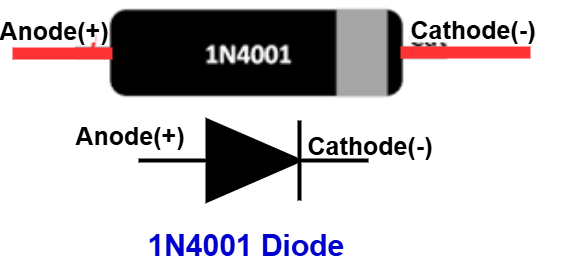
The diode 1N4001 datasheet specifies a simple two-terminal configuration consisting of an anode (A) and cathode (K).
- Anode (A): The positive terminal where the current enters the diode. When connected to a higher voltage than the cathode, the diode becomes forward-biased and allows current to flow.
- Cathode (K): The negative terminal where the current exits the diode. The cathode side is easily identified by a silver band on the diode’s body.
In a circuit, the 1N4001 diode is placed so that current flows from the anode to the cathode, enabling rectification in AC to DC conversion. This DO-41 package diode is widely used in rectifier circuits, power supplies, and polarity protection applications due to its efficiency and reliability.
Features & Specifications
The datasheet 1N4001 provides the following technical specifications:
- Maximum Repetitive Reverse Voltage: 50V
- Maximum Forward Continuous Current: 1A
- Peak Forward Surge Current: 30A (for 8.3ms single half-sine wave)
- Forward Voltage Drop: 0.7V at 1A
- Reverse Recovery Time: 30µs (typical)
- Maximum Reverse Current: 5µA at 25°C, 50µA at 100°C
- Junction Capacitance: 15pF at 1MHz
- Operating Temperature Range: -55°C to +150°C
- Storage Temperature Range: -55°C to +175°C
- Thermal Resistance (Junction to Ambient): 50°C/W
- Thermal Resistance (Junction to Lead): 15°C/W
- Power Dissipation: 3W (max)
- Mounting Type: Through-hole (Axial Lead)
- Package Type: DO-41 (Axial Leaded)
- Polarity Indicator: Silver band marking the cathode side
These features make the 1N4001 diode a reliable choice for power rectification, polarity protection, and voltage-blocking applications in low-frequency circuits.
How to Use the 1N4001 Diode in a Circuit?
The 1N4001 diode is a widely used power diode for rectification applications and is part of the 1N400x series. It is commonly found in rectifier circuits such as half-wave and full-wave rectifiers, as well as diode clipper circuits, where it helps convert an AC voltage source into a specific DC voltage level.
Now, let’s explore how the 1N4001 diode functions in a simple half-wave rectifier circuit. This silicon diode requires a voltage drop of 0.7V across it to operate effectively.
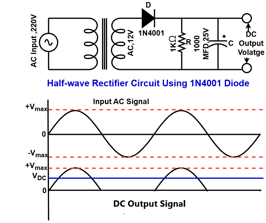
The circuit diagram and output characteristics of the half-wave rectifier are shown below.
Components Required:
- 1N4001 Diode
- Step-down Transformer (220V to 12V)
- Load Resistor (1kΩ)
- Capacitor (1000µF, 25V)
In this rectifier circuit, a step-down transformer (220V to 12V) first reduces the high AC voltage to a lower level suitable for rectification. The 1N4001 diode, connected in series with the load resistor, allows unidirectional current flow, converting AC to pulsating DC.
During the positive half-cycle of the AC input, the anode of the diode is positive with respect to the cathode, putting the diode in forward bias. This allows the current to flow through the DC load resistor, making the output voltage (Vout) equal to the supply voltage (Vs), i.e., Vout = Vs.
In the negative half-cycle, the diode becomes reverse-biased as the anode is now negative with respect to the cathode. This means the diode is open-circuited, and no current flows through the circuit, resulting in zero output voltage across the load resistor. Since current flows only in one direction, this circuit is referred to as unidirectional rectification.
The output characteristics show that the positive half-cycle of the AC input is converted to DC, while the negative half-cycle is blocked. The output DC voltage can be estimated using the following formula:
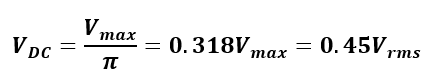
where:
- Vmax is the maximum applied AC voltage.
- VDC is the output DC voltage level.
- Vrms is the root mean square value of the applied voltage.
Since the rectified DC voltage still contains ripples, a smoothing capacitor (1000µF, 25V) is connected parallel to the resistor to filter out fluctuations and provide a steady DC output. The 1kΩ resistor helps regulate the voltage and limit current surges.
This rectification process using the 1N4001 diode is widely used in power supplies, battery chargers, and low-power DC applications.
Equivalent Diodes & Alternatives
The alternative or equivalent diodes for the 1N4001 include various options with similar or enhanced characteristics. Some of these alternatives are:
- 1N4002 (100V), 1N4003 (200V), 1N4004 (400V), 1N4007 (1000V) — same series, different voltage ratings.
- 1N5408 — similar diode with a higher current rating (3A).
- Schottky Diodes (e.g., 1N5819) — for applications needing faster switching and lower voltage drop.
Where to Use/Applications
The 1N4001 diode is widely used in various electronic applications, including:
- Power Rectifiers – Converts AC to DC in power supplies.
- Voltage Blocking – Prevents unwanted voltage flow in DC circuits.
- Reverse Polarity Protection – Protects battery-powered devices from incorrect polarity.
- Snubber Circuits – Used in relay and motor protection circuits.
- Flyback Diodes – Prevent voltage spikes in inductive loads like motors and solenoids.
- Bridge Rectifiers -Used in full-wave rectifier circuits for efficient AC-to-DC conversion.
- Solar Panel Protection – Prevents reverse current flow in solar charging systems.
- Charger Circuits – Used in battery chargers, adapters, and power banks.
Advantages & Disadvantages
Advantages:
- Cost-effective and easily available
- Reliable for low-power applications
- Low forward voltage drop (0.7V)
- Handles high surge currents
Disadvantages:
- Limited frequency response (not suitable for high-speed switching)
- Low reverse voltage rating (only 50V; higher models in the series are needed for more voltage)
- Slow recovery time compared to Schottky diodes
Conclusion
The 1N4001 diode is a widely used general-purpose rectifier diode in power electronics. It is cost-effective, reliable, and easy to use in AC-DC conversion, polarity protection, and voltage blocking applications. With a 1A current rating and 50V reverse voltage, it is ideal for low-voltage rectification but not suitable for high-frequency circuits. The diode 1N4001 datasheet provides all the necessary specifications for use in electronic projects.
Read Next: