Diode polarity refers to the orientation of a diode in an electrical circuit and determines whether the device is forward-biased or reverse-biased. A diode has two terminals, the anode and cathode, and its behavior depends on the voltage applied across these terminals.
When the anode is at a higher potential than the cathode, the diode is forward-biased and allows conventional current to flow from the anode toward the cathode. When the cathode is at a higher potential than the anode, the diode is reverse-biased and normally blocks current, apart from a small leakage current.
Understanding diode polarity is important when installing or testing a diode because connecting it in the wrong orientation can prevent a circuit from operating correctly or, in some cases, damage the component.
Forward Polarity of a Diode
A diode is forward-biased when the anode is connected to a more positive potential than the cathode. Under this condition, the PN junction barrier is reduced and the diode conducts current.
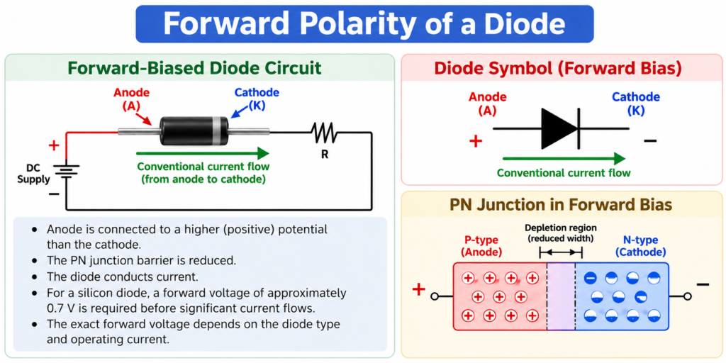
For a typical silicon diode, a forward voltage of approximately 0.7 V is required before significant current flows. The exact forward voltage depends on the diode type and operating current.
Reverse Polarity of a Diode
A diode is reverse-biased when the cathode is connected to a more positive potential than the anode. In this condition, the junction opposes current flow and only a very small reverse leakage current normally flows.
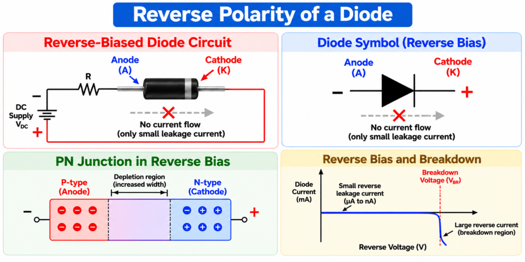
If the reverse voltage exceeds the diode’s rated breakdown voltage, the diode may enter breakdown. Whether this is safe depends on the type of diode and the circuit design. For example, Zener diodes are specifically designed to operate in their reverse-breakdown region.
How to Identify Diode Polarity
There are several ways to identify the polarity of a diode, depending on its type and package.
1. Check the Physical Marking
In many conventional through-hole diodes, a band or stripe on the diode body marks the cathode (K). The opposite, unmarked terminal is the anode (A).
For an LED, the longer lead is usually the anode, while the shorter lead is the cathode. A flat edge on the LED body commonly indicates the cathode side.
2. Check the Diode Symbol
The circuit symbol can also be used to identify diode polarity. The straight bar represents the cathode, while the opposite side represents the anode.
This makes the symbol particularly useful when identifying diode polarity from a circuit diagram.
3. Use a Multimeter
A digital multimeter can be used to identify the anode and cathode of an unknown diode. Set the meter to diode-test mode and connect the probes across the diode.
- If the meter displays a forward voltage drop, the red probe is connected to the anode and the black probe to the cathode.
- If the meter displays OL or a similar open-circuit indication, reverse the probes. The diode is then reverse-biased.
- For a typical silicon PN-junction diode, the forward voltage is commonly around 0.6–0.7 V, although the actual value varies with diode type and test current.
This method is especially useful when the diode’s physical markings are unclear or the component has been removed from a circuit.
Tips and Precautions
- Switch off the circuit power before testing a diode with a multimeter. For in-circuit testing, also allow capacitors to discharge before taking measurements.
- If the diode’s marking is unclear or damaged, use the multimeter’s diode-test mode to identify its polarity.
- When testing an LED, remember that its forward voltage varies with the LED type and color, so do not expect the same voltage drop for every LED.
- Always check the anode and cathode orientation before installing a diode. Incorrect polarity can prevent the circuit from working properly and may damage the diode or other components in some circuits.
- For SMD diodes, do not assume that every package uses the same marking convention. Check the component datasheet when the polarity marking is unclear.
Why Diode Polarity is Important
Correct diode polarity is essential in circuits such as rectifiers, voltage regulators, protection circuits, switching circuits, and signal-processing circuits. A diode installed in the wrong direction may block the required current or cause the circuit to behave differently from its intended operation.
Therefore, always check the anode, cathode, and polarity marking before installing a diode in a circuit.
Conclusion
Diode polarity determines how a diode behaves when voltage is applied across its terminals. With the anode more positive than the cathode, the diode is forward-biased and conducts current. With the cathode more positive than the anode, it is reverse-biased and normally blocks current. Correctly identifying diode polarity is therefore essential for reliable and safe electronic circuit operation.
Read Next:
- Schottky Diode vs Zener Diode
- Difference Between BJT and MOSFET
- Difference Between Diode and Rectifier
- Difference Between Diode and Transistor
- Difference Between Silicon Diode and Germanium Diode
- Diode Voltage Drop: Formula, Values, Chart, Table & Measurement
- Diode Turn-On Voltage: Definition, Values & Examples
- Diode Symbol: Meaning, Types, Circuit Examples
- Diode Terminals: Anode and Cathode Explained
- Reverse Leakage Current: Definition, Causes, Factors, and Measurement
- Charge Carriers: Definition, Types, Examples, and Working