This article explains how to test a diode using a digital multimeter in two test modes. The two test modes are as follows.
- Diode Test mode: This is the best approach if a multimeter has Diode Test Mode it must be used.
- Resistance mode: This method is usually employed when a multimeter does not have a Diode Test mode.
In order to test a diode, it may be necessary to remove one end of it from the circuit.
Here are some important things to keep in mind when testing diodes using the Resistance mode:
- The value of resistance is not always a reliable indicator of a diode’s health.
- It should not be used when a diode is connected to a circuit since it can cause a false reading.
- After a Diode Test indicates a diode is bad, it can be used to verify if it is bad in a specific application.
Diode Test Mode
A diode can be tested by measuring the voltage drop across it when forward-biased. A diode acts as a closed switch when forward-biased, allowing current to flow.
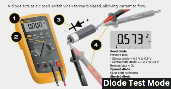
A multimeter’s Diode Test mode generates a small voltage between the test leads and displays the voltage drop across a diode when forward-biased. To conduct the Diode Test, connect the test leads across the diode and observe the displayed voltage drop. The test procedure is listed below.
- Make certain
- The circuit is not receiving any power at the moment.
- No voltage is present at the diode. If there is voltage in the circuit due to charged capacitors, they need to be discharged. To confirm the presence of voltage, set the multimeter to measure the required AC or DC voltage and take a reading.
- Switch the dial to Diode Test mode, which might share the space with another function.
- Connect the test leads to the diode and make a note of the measurement displayed.
- Switch the test leads and note down the measurement displayed.
Diode Test Analysis
- A typical voltage drop for a forward-based diode ranges from 0.2 to 0.8 volts, depending on the type. Silicon diodes commonly have a voltage drop ranging from 0.5 to 0.8 volts, while germanium diodes typically have a voltage drop ranging from 0.2 to 0.3 volts.
- The diode is functioning as an open switch when a good diode is reverse-biased, indicated by the multimeter displaying OL.
- A bad open diode does not allow current to flow in either direction, resulting in an OL reading on a multimeter.
- A diode with a short circuit has a voltage drop reading of approximately 0.4 V in both directions.
Resistance Test Mode
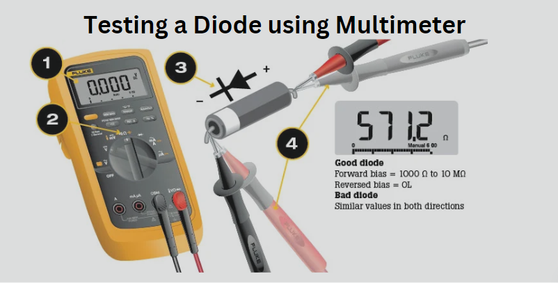
Set the multimeter to Resistance mode (Ω) for additional diode testing or if a multimeter lacks the Diode Test mode.
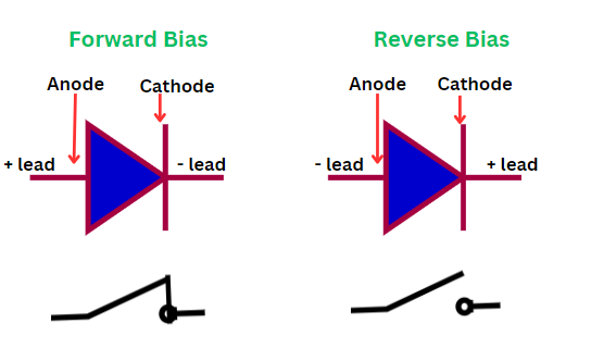
A diode is forward-biased when the anode is connected to the positive test lead(Red) and the cathode is connected to the negative test lead(black).
- A good diode has resistance in the range of from 1000 Ω to 10 MΩ when forward biased.
- The high resistance of the diode is caused by the current flowing through the diode when it is forward-biased. Therfore, high resistance measuring multimeter is required for testing.
- The diode is considered bad if multimeter readings are the same in both directions when testing the reverse-biased resistance.
A diode is considered reverse-biased when the negative (black) test lead is connected to the anode and the positive (red) test lead is connected to the cathode.
The resistance mode procedure should be conducted in the following manner.
- Make certain
- The circuit is not receiving any power at the moment.
- No voltage is present at the diode. If there is voltage in the circuit due to charged capacitors, they need to be discharged. To confirm the presence of voltage, set the multimeter to measure the required AC or DC voltage and take a reading.
- Set the dial to Resistance mode (Ω), which may share a space with another function.
- After removing the diode from the circuit, connect the test leads and record the measurement displayed.
- Reverse the test leads and note down the measurement displayed.
- Compare readings with a known good diode for better accuracy when using Resistance mode to test diodes.
Reference: Digital Multimeter Principles by Glen A. Mazur, American Technical Publishers.