A diode symbol is a graphical representation used in electrical and electronic circuit diagrams to show the presence, orientation, and function of a diode. Since a diode permits conventional current to flow primarily in one direction, its symbol also helps us understand how the component should be connected in a circuit.
Knowing how to identify a diode symbol is important when reading circuit schematics, designing electronic circuits, troubleshooting equipment, or converting a schematic into a physical PCB.
In this guide, we will explain the diode symbol, its polarity, common types of diode symbols, forward and reverse bias, practical circuit applications, and how to correctly interpret a diode in a schematic.
What Is a Diode Symbol?
A diode symbol is the standard graphical representation of a diode used in electrical schematics. It indicates both the presence of the diode and its direction of conduction.
A conventional diode has two terminals:
- Anode
- Cathode
The symbol provides a quick visual indication of these two terminals. The cathode is represented by the line or bar at one end of the symbol, while the opposite side represents the anode.
Because a diode is a polarized component, its orientation is important. Connecting it in the wrong direction can prevent the circuit from operating correctly or, in some applications, may result in component damage.
The symbol therefore acts as a simple visual guide for understanding the intended current path.
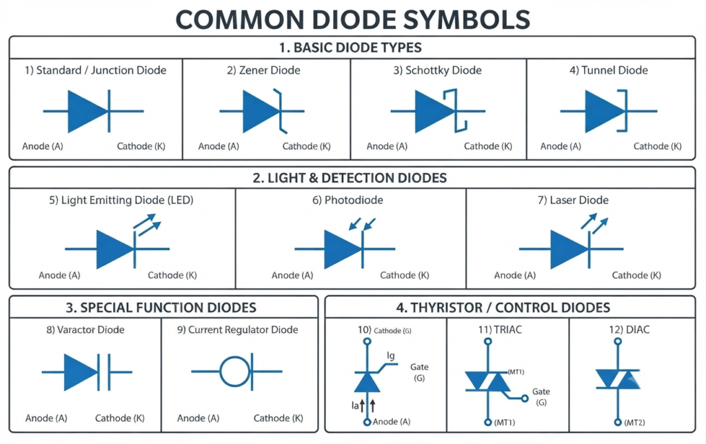
Types of Diode Symbols
Different diode technologies perform different functions, so their schematic symbols contain small variations that distinguish them from a standard diode.
Some commonly encountered diode-related symbols include:
| Diode Type | Symbol Identification | Main Application |
| Standard PN Junction Diode | Basic diode symbol with a straight cathode bar | Rectification, switching and protection |
| Zener Diode | Cathode line has bent edges | Voltage regulation and voltage reference |
| LED | Diode symbol with arrows pointing outward | Light emission and indication |
| Schottky Diode | Modified cathode marking | Fast switching and low forward voltage |
| Photodiode | Diode symbol with arrows pointing inward | Light sensing |
| Tunnel Diode | Modified cathode structure | High-frequency and microwave circuits |
| Varactor Diode | Diode symbol combined with capacitor-like plates | Electronic tuning and frequency control |
| Current Regulator Diode | Diode symbol associated with constant-current operation | Current regulation |
| SCR | Diode structure with a gate terminal | Controlled rectification and switching |
| DIAC | Bidirectional diode symbol | Triggering AC switching devices |
| TRIAC | Bidirectional switching device with a gate | AC power control |
Although these devices may look similar in a circuit diagram, the additional markings provide important information about their operating principle.
1. Standard Diode Symbol
The standard diode symbol represents a conventional PN junction diode. It is one of the most frequently used diode symbols in circuit diagrams.
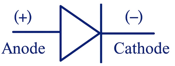
The symbol identifies the anode and cathode and shows the direction in which conventional current can normally flow when the diode is forward biased.
Standard diodes are commonly used for:
- AC-to-DC rectification
- Reverse-polarity protection
- Signal routing
- Switching circuits
- Freewheeling and flyback protection
For example, four standard diodes can be connected as a bridge rectifier to convert an AC supply into pulsating DC.
2. Zener Diode Symbol
The Zener diode symbol resembles the standard diode symbol, but its cathode line has distinctive bent or irregular edges.
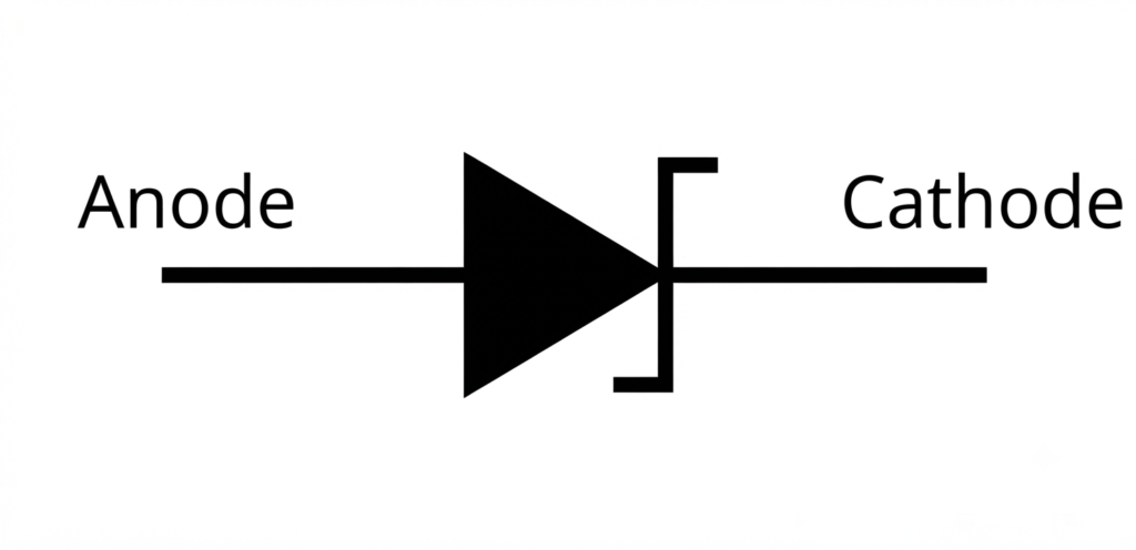
This modification identifies the device as a Zener diode.
A Zener diode is specifically designed to operate in the reverse-bias region once the applied voltage reaches its specified Zener breakdown voltage.
Zener diodes are widely used for:
- Voltage regulation
- Voltage reference circuits
- Overvoltage protection
- Voltage clamping
- Protecting sensitive electronic components
Unlike an ordinary diode, which is generally used to block reverse current, a Zener diode can intentionally conduct in the reverse direction under controlled conditions.
3. LED Symbol
An LED (Light Emitting Diode) uses a diode symbol with two arrows directed outward from the diode.
The outward arrows indicate that the component produces or emits light when it is forward biased.
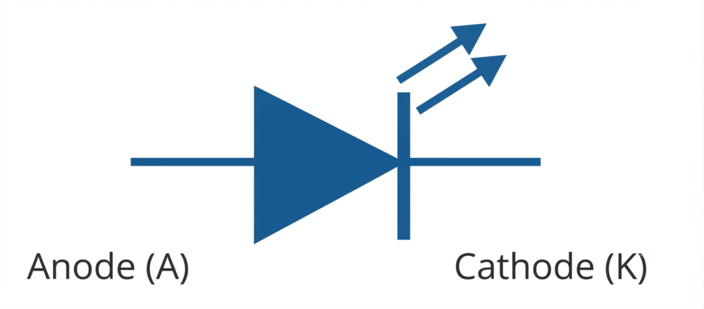
LEDs are available in different colors and are commonly used wherever visual indication or illumination is required.
Typical applications include:
- Power indicators
- Status indicators
- Display systems
- Lighting
- Automotive electronics
- Optical communication
An LED normally requires a suitable current-limiting resistor or an appropriate current-control circuit to prevent excessive current from damaging the device.
4. Schottky Diode Symbol
A Schottky diode is represented by a modified diode symbol with distinctive markings around the cathode.
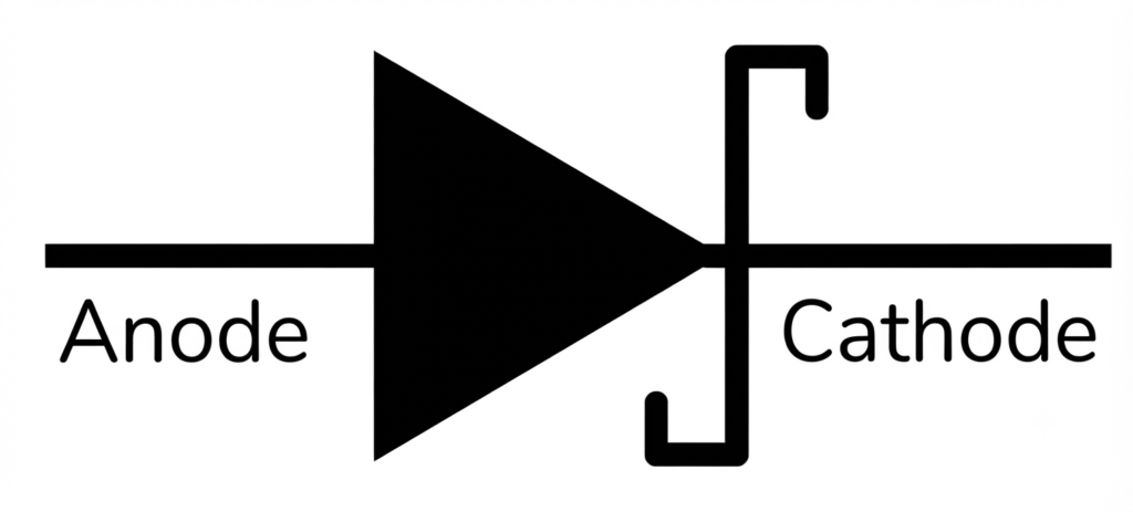
Schottky diodes are known for their relatively low forward voltage and rapid switching characteristics.
These properties make them particularly useful in circuits where switching losses and speed are important.
Schottky diodes are commonly used in:
- High-speed switching circuits
- Switching power supplies
- DC-DC converters
- Rectifier circuits
- Protection circuits
- High-frequency electronic systems
Their lower forward voltage can also help reduce conduction losses compared with many conventional PN junction diodes.
5. Photodiode Symbol
A photodiode uses a diode symbol with two arrows pointing toward the diode.
The inward arrows represent incoming light falling on the semiconductor junction.
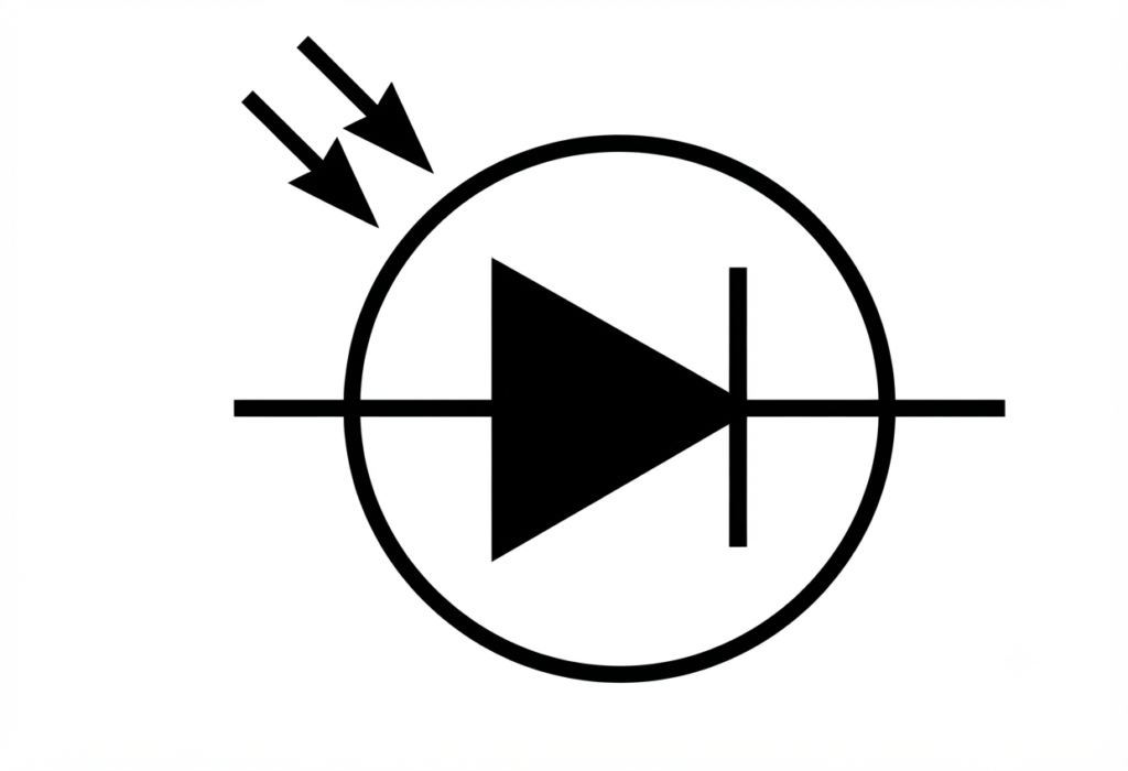
A photodiode converts incident light into an electrical response, making it useful for detecting or measuring light intensity.
Photodiodes are used in:
- Optical sensors
- Remote-control receivers
- Light measurement systems
- Optical communication
- Smoke detectors
- Industrial sensing equipment
The direction of the arrows is a useful way to distinguish a photodiode symbol from an LED symbol.
6. Tunnel Diode Symbol
A tunnel diode has a modified diode symbol that identifies its special junction structure.
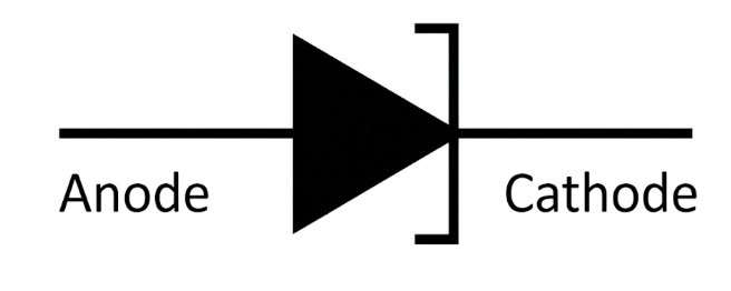
Tunnel diodes operate using quantum mechanical tunneling and can respond extremely quickly. Their characteristics make them useful in certain high-frequency and microwave applications.
Tunnel diodes is used in:
- High-frequency oscillators
- Microwave circuits
- High-speed switching
- Specialized communication circuits
They are less common in general-purpose electronic circuits but remain important in specific high-frequency applications.
7. Varactor Diode Symbol
A varactor diode, also called a varicap diode, is represented by a diode symbol combined with capacitor-like markings.

It is normally operated under reverse bias, where its junction capacitance changes with the applied voltage.
This voltage-dependent capacitance allows the diode to perform the function of a variable capacitor without mechanical adjustment.
Varactor diodes are used in:
- Electronic tuning circuits
- Radio receivers
- Voltage-controlled oscillators
- Frequency synthesizers
- RF circuits
- Television tuning systems
The symbol helps identify that the component provides a capacitance-related function controlled by voltage.
8. Current Regulator Diode Symbol
A current regulator diode, sometimes called a constant-current diode, is designed to maintain a relatively constant current over a specified range of voltage.
Its schematic representation identifies it as a special type of diode intended for current regulation rather than ordinary rectification.
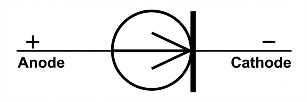
Current regulator diodes can be used for:
- Constant-current sources
- LED current control
- Biasing circuits
- Simple current regulation
- Electronic protection circuits
The basic purpose is different from a Zener diode. A Zener is primarily associated with maintaining a voltage, whereas a current regulator diode is designed to control current.
10. Backward Diode Symbol
A backward diode is a special type of diode that exhibits tunnel-diode-like behavior under forward bias and Zener-diode-like behavior under reverse bias. Its tunneling and breakdown voltages are much lower than those of conventional devices.
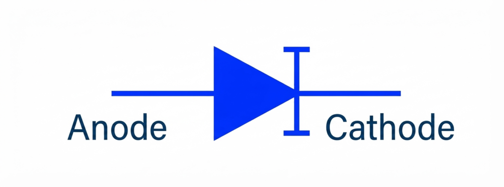
The backward diode is designed to conduct effectively at very small voltage levels, making it useful for detecting and rectifying low-amplitude signals.
It is particularly suitable for applications where the signal voltage is too small for a conventional PN junction diode to provide efficient rectification.
Backward diodes are commonly used in:
- Low-voltage signal rectification
- Small-signal detection circuits
- High-frequency detector circuits
- Microwave and RF applications
- Sensitive signal-processing circuits
A backward diode can be especially useful for rectifying very small AC signals, typically in the range of 0.1 to 0.6 V, because its reduced voltage thresholds allow conduction at lower signal levels.
11. PIN Diode
A PIN diode is a special type of diode that has a P-type layer, an intrinsic (I) layer, and an N-type layer between its terminals. The intrinsic region increases the diode’s ability to handle high-frequency signals and provides useful switching characteristics.
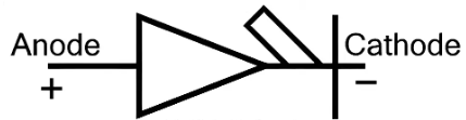
The PIN diode uses a diode symbol similar to a conventional PN junction diode, but its internal construction includes the additional intrinsic layer.
PIN diodes are known for their low capacitance and fast switching characteristics, making them particularly useful in high-frequency and RF circuits.
PIN diodes are commonly used in:
- RF switching circuits
- High-frequency signal control
- RF attenuators
- Microwave circuits
- Antenna switching
- Signal modulation circuits
- Photodetectors
When forward biased, a PIN diode can act as a low-resistance path for RF signals, while under reverse bias, it provides high impedance. This makes it useful for controlling and switching high-frequency signals.
12. SCR Symbol
An SCR (Silicon Controlled Rectifier) is a controlled semiconductor switching device with three terminals:
- Anode
- Cathode
- Gate
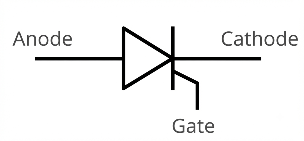
Its symbol resembles a diode but includes an additional gate connection.
Unlike an ordinary diode, an SCR does not simply begin conducting whenever it is forward biased. It can be triggered by applying an appropriate signal to its gate.
SCRs are widely used in:
- Controlled rectifiers
- Motor control
- Battery chargers
- Power controllers
- Industrial switching systems
- Heater control circuits
SCRs are particularly useful where controlled one-way power switching is required.
13. DIAC Symbol
A DIAC is a bidirectional semiconductor device used mainly for triggering AC switching circuits.
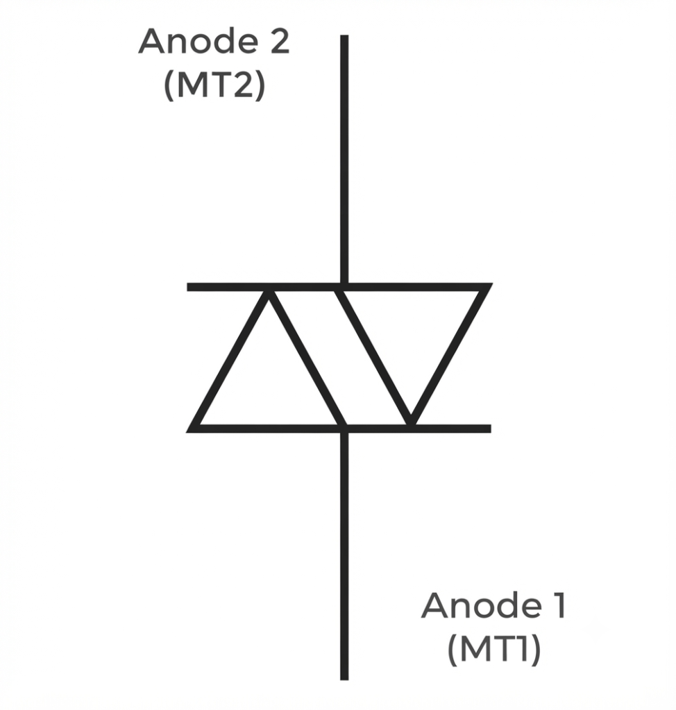
Its symbol represents conduction in both directions after the applied voltage reaches the required breakover level.
Unlike a conventional diode, a DIAC does not have a simple one-way conduction characteristic.
DIACs are commonly used to trigger TRIACs in AC control circuits.
For example, they can be found in phase-control circuits used for controlling:
- Lamp brightness
- Fan speed
- Motor speed
- AC power
14. TRIAC Symbol
A TRIAC is a bidirectional semiconductor switching device used for controlling AC power.
Its symbol represents two-way current conduction and includes a gate terminal for triggering the device.
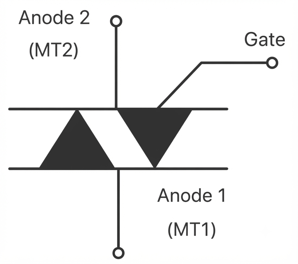
Because AC current alternates direction, the bidirectional nature of a TRIAC makes it useful for controlling both portions of an AC waveform.
TRIACs are commonly found in:
- Light dimmers
- Fan regulators
- AC motor speed controllers
- Heater controllers
- Domestic appliance control circuits
Diode Symbol Polarity: Anode and Cathode
Understanding diode symbol polarity is essential when interpreting an electrical schematic.
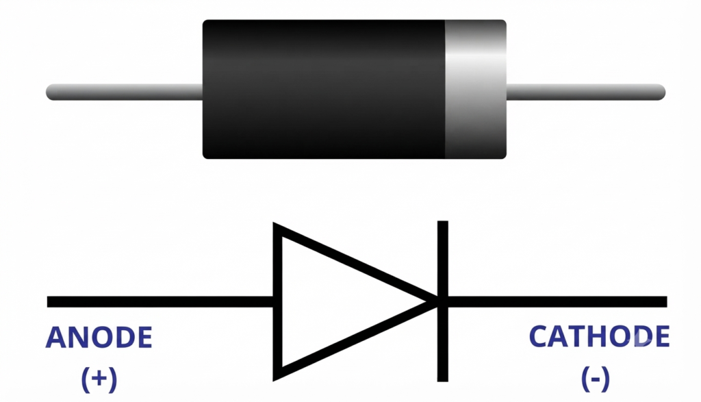
A diode has two terminals:
Anode
The anode is the terminal on the conducting side of the standard diode symbol.
Cathode
The cathode is identified by the line or bar in the diode symbol.
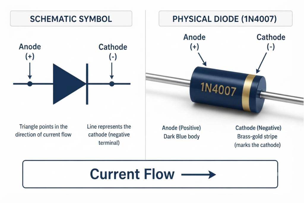
A simple way to remember the physical component is that many conventional through-hole diodes have a stripe or band on the body indicating the cathode.
Therefore, when moving from a circuit diagram to the actual component, the cathode marking on the physical diode should correspond to the cathode marking shown in the schematic.
Direction of Current in a Diode
For conventional current, the normal forward-current direction is:
Anode → Cathode
When the anode is at a higher potential than the cathode by a sufficient amount, the diode becomes forward biased and conducts current.
When the cathode is at a higher potential than the anode, the diode is reverse biased and normally blocks current, apart from a small reverse leakage current.
Understanding this direction is particularly important when troubleshooting protection, rectifier, switching, and signal circuits.
Forward Bias and Reverse Bias
The operating condition of a diode depends largely on the voltage polarity applied across its terminals.
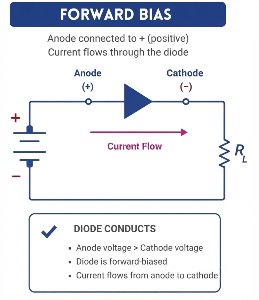
Forward Bias
A diode is forward biased when the anode is at a higher potential than the cathode.
Under normal operating conditions:
- The diode conducts current.
- Its resistance to current flow becomes relatively low.
- It can be considered similar to a closed switch in simplified circuit analysis.
For a practical silicon diode, the forward voltage is commonly around 0.7 V, although the actual value depends on current, temperature, and diode type.
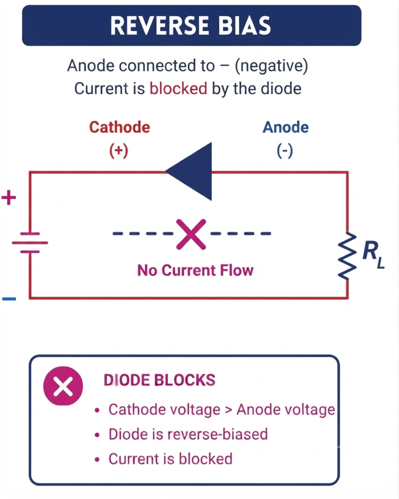
Reverse Bias
A diode is reverse biased when the cathode is at a higher potential than the anode.
Under normal conditions:
- The diode blocks most current.
- Only a small leakage current flows.
- It can be approximated as an open switch in basic circuit analysis.
If the reverse voltage becomes sufficiently high, certain diode types may intentionally or unintentionally enter breakdown.
Diode Symbol in Practical Circuit Diagrams
A diode symbol becomes much more useful when we understand how it appears in real circuits.
Some common applications are described below.
1. LED Indicator Circuit
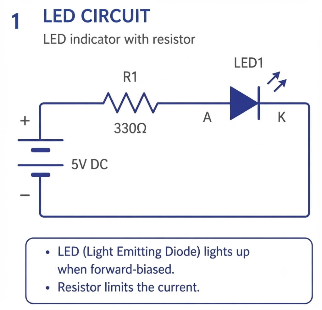
An LED conducts when it is correctly forward biased and produces light.
A current-limiting resistor is normally connected in series with the LED to control the current through it.
For example, LEDs are frequently used as power-on indicators in electronic equipment.
2. Bridge Rectifier
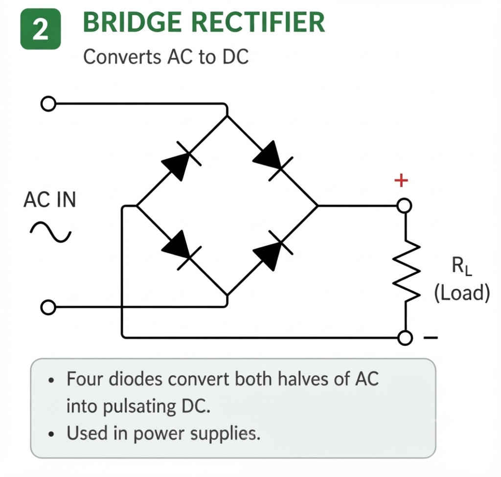
A bridge rectifier normally uses four diodes arranged so that both halves of an AC waveform contribute to the output.
The circuit converts an AC input into a pulsating DC output, which can then be filtered and regulated to obtain a smoother DC supply.
Bridge rectifiers are widely used in power supplies and battery chargers.
3. Reverse Polarity Protection
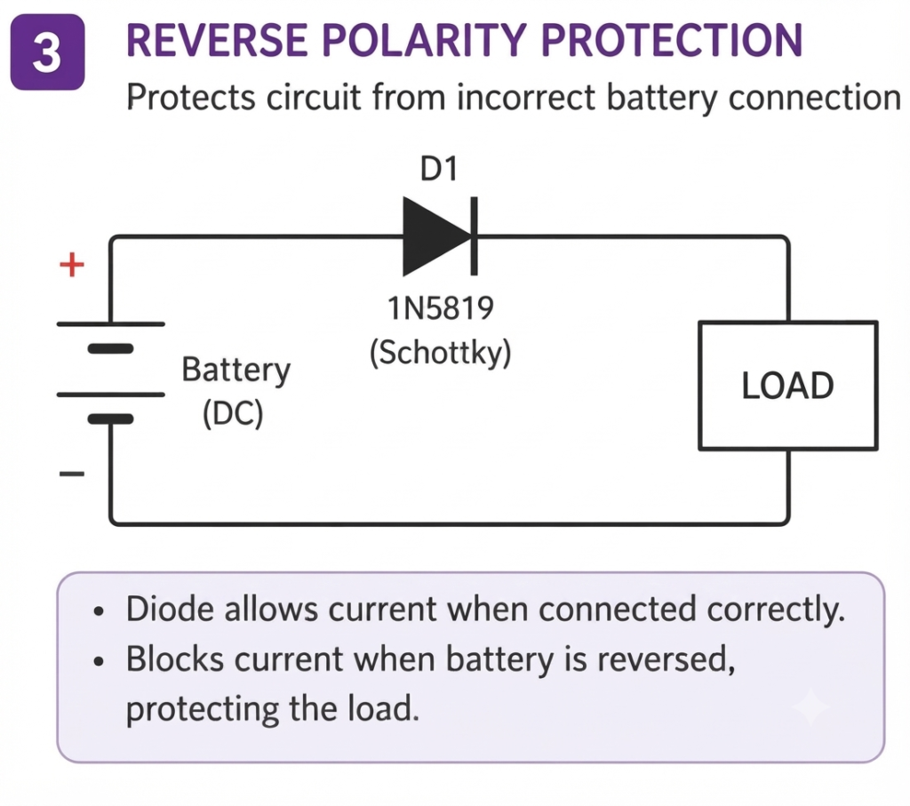
A diode can be used to prevent damage when a DC supply or battery is accidentally connected with reversed polarity.
The diode arrangement is selected so that normal polarity allows the required power to reach the circuit while reverse polarity is blocked.
This technique is useful for protecting electronic boards and sensitive components.
4. Flyback Diode
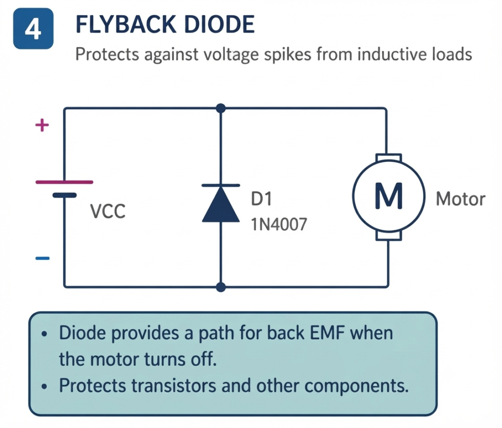
Inductive loads such as motors, relays, solenoids, and contactor coils can generate a high-voltage transient when their current is suddenly interrupted.
A flyback diode provides a controlled path for the stored inductive energy.
The diode is normally connected across the inductive load and is reverse biased during normal operation. When the supply is switched off, the induced voltage changes the diode’s operating condition and allows the stored energy to circulate safely.
This helps protect switching devices and control electronics from voltage spikes.
How to Read a Diode Symbol in a Schematic
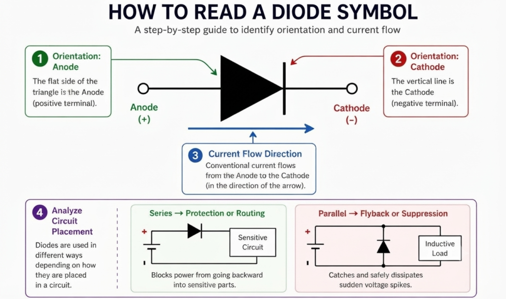
You can identify a diode and understand its intended operation by following a few simple steps.
Step 1: Identify the Diode Symbol
First locate the diode symbol in the schematic.
Find the conducting side and the cathode line. The cathode is the side represented by the bar.
Step 2: Identify the Diode Type
Check whether the symbol is a standard diode or a modified version.
Special markings may indicate:
- Zener diode
- LED
- Schottky diode
- Photodiode
- Varactor diode
- SCR
- Other special semiconductor devices
The reference designation can also provide useful information. For example, a schematic may use designators such as D1, D2, or ZD1, depending on the circuit convention.
Step 3: Determine the Current Direction
Determine the voltage polarity across the diode.
For a standard diode, conventional current normally flows from the anode toward the cathode when the diode is forward biased.
Step 4: Examine Its Position in the Circuit
The location of a diode often gives clues about its purpose.
A diode connected in series with a power path may be used for:
- Rectification
- Protection
- Isolation
- Signal routing
A diode connected across an inductive load may be used for:
- Flyback protection
- Voltage suppression
- Transient control
Diode Symbol vs Other Electronic Symbols
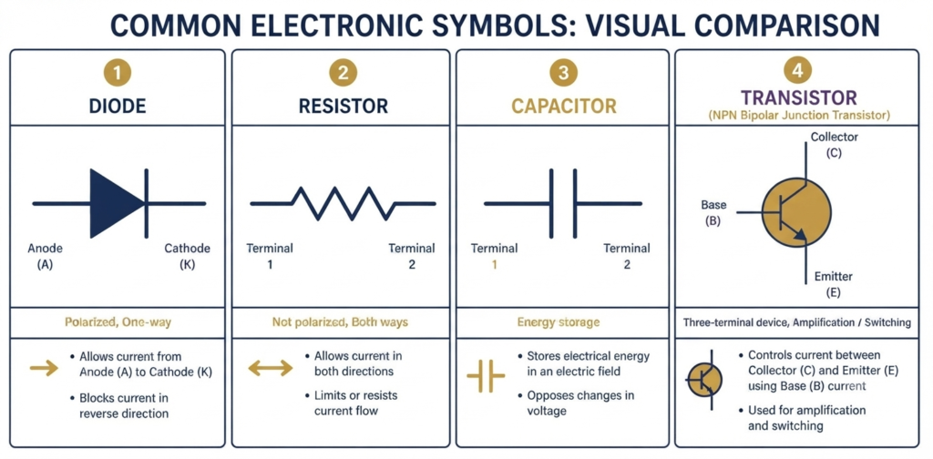
When reading a schematic, it is important not to confuse a diode with other components.
Diode vs Resistor
A resistor is normally represented by a zigzag or rectangular symbol, depending on the drawing standard.
A resistor:
- Is generally non-polarized
- Restricts current
- Produces a voltage drop according to Ohm’s law
A diode, in contrast, is polarized and has directional current-conduction characteristics.
Diode vs Capacitor
A capacitor is represented by two plates or lines separated by a gap.
A capacitor stores electrical energy in an electric field.
Some capacitors are polarized, such as electrolytic capacitors, while many others are non-polarized.
A diode, however, is primarily used for directional conduction, rectification, switching, protection, or other semiconductor functions.
Diode vs Transistor
A transistor normally has three terminals and is represented using a more complex symbol.
Depending on the transistor type, the terminals may be:
- Base
- Collector
- Emitter
or:
- Gate
- Drain
- Source
Transistors are widely used for switching and amplification, while a conventional diode has two terminals.
Common Mistakes When Reading Diode Symbols
Beginners often make a few simple mistakes when working with diode symbols.
1. Confusing the Anode and Cathode
One of the most common mistakes is reversing the two terminals.
Always identify the cathode bar in the schematic before connecting the physical diode.
On many physical diodes, the cathode is marked by a stripe or band.
2. Ignoring Polarity
A diode cannot normally be connected in either direction without considering its operating requirements.
Incorrect polarity may:
- Prevent current from flowing
- Stop a circuit from operating
- Cause unexpected circuit behavior
- Damage the diode or other components in certain conditions
3. Confusing an LED With a Standard Diode
The LED symbol contains additional arrows pointing outward.
A standard diode does not have these light-emission arrows.
Selecting the wrong component symbol can lead to confusion during circuit assembly and component procurement.
4. Assuming Every Diode Is Used for Rectification
Not every diode is primarily intended for AC-to-DC conversion.
Different diode types are optimized for different functions, including:
- Voltage regulation
- Light emission
- Light detection
- High-speed switching
- Current regulation
- AC power control
- Voltage-dependent capacitance
The symbol’s additional markings can help identify the intended function.
Importance of Diode Symbols in PCB Design
A diode symbol is not only useful for understanding a circuit diagram. It is also an important part of the transition from circuit design to a physical printed circuit board.
The basic workflow can be understood as:
Schematic symbol → Component footprint → PCB placement → Physical component
First, the correct diode symbol is placed in the schematic. The symbol is then associated with a suitable footprint for the selected component.
The footprint must match the actual package, such as:
- Through-hole
- SMD
- Specific diode package dimensions
During PCB layout, the physical orientation of the diode must correspond correctly with the schematic polarity.
A mismatch between the schematic and physical component orientation can result in an incorrectly assembled board.
Diode Symbol and Physical Diode Marking
When assembling a circuit, the schematic symbol should always be compared with the marking on the actual component.
For a conventional diode:
- Schematic cathode bar = physical cathode marking
- Opposite terminal = anode
The physical marking may appear as a stripe, band, notch, or another manufacturer-specific polarity indicator.
For SMD components, polarity markings vary by package and manufacturer, so the component datasheet should be checked whenever there is uncertainty.
Why Understanding the Diode Symbol Is Important
The diode symbol provides several important pieces of information at a glance.
It helps an engineer determine:
- The type of semiconductor device being used.
- The polarity of the component.
- The intended direction of current flow.
- How the component is expected to behave in the circuit.
- How the physical component should be oriented.
- What role the diode may perform in the circuit.
This makes the diode symbol an essential part of schematic interpretation and electronic circuit design.
Conclusion
The diode symbol is a simple but important element of electrical and electronic circuit diagrams. It identifies the diode, indicates its polarity, and provides information about its intended operation.
The standard diode symbol is used for applications such as rectification, switching, and protection, while modified symbols identify devices such as Zener diodes, LEDs, Schottky diodes, photodiodes, varactor diodes, tunnel diodes, SCRs, DIACs, and TRIACs.
The most important point to remember when reading a diode symbol is the relationship between the anode and cathode. Correctly identifying these terminals makes it much easier to understand forward bias, reverse bias, current direction, and the diode’s role within a circuit.
Once the symbol is understood, the same knowledge can be applied when selecting the component, assigning its PCB footprint, placing it on a circuit board, and troubleshooting the finished electronic system.
Read Next:
- Schottky Diode vs Zener Diode
- Difference Between BJT and MOSFET
- Difference Between Diode and Rectifier
- Difference Between Diode and Transistor
- Difference Between Silicon Diode and Germanium Diode
- Diode Voltage Drop: Formula, Values, Chart, Table & Measurement
- Diode Turn-On Voltage: Definition, Values & Examples