A half-wave rectifier allows current to flow through it only in one direction, converting alternating current (AC) to direct current (DC). We call this process of conversion “rectification.” This effect is usually achieved using a single PN diode in a half-wave rectifier circuit. The diode blocks the negative half-cycle of the AC input, which only conducts current during the positive half-cycle. A pulsating DC output is produced as a result, with the output waveform consisting of a succession of positive half-cycles and the suppression of the negative half-cycles.
This article will explain half-wave rectifiers—what they are, how they operate, how they are used, and their drawbacks.
What is Half Wave Rectifier?
A half-wave rectifier is an electronic circuit that converts alternating current (AC) into direct current (DC). It does this by allowing the AC signal to pass only during one half of each cycle, usually the positive half. A single p-n junction diode is typically used in this circuit to achieve this conversion. When the AC input voltage is positive, the diode conducts and allows current to pass through, generating a positive voltage at the output. When the AC input voltage is negative, the diode blocks current flow, producing no output voltage.
A half-wave rectifier converts alternating current (AC) into direct current (DC). It allows the AC signal to pass only during the positive half-cycle of each cycle. A single p-n junction diode converts the AC into DC. When the AC input voltage is positive, the diode conducts, allows current to pass through, and generates a positive voltage at the output. When the AC input voltage is negative, the diode blocks current flow, producing no output voltage.
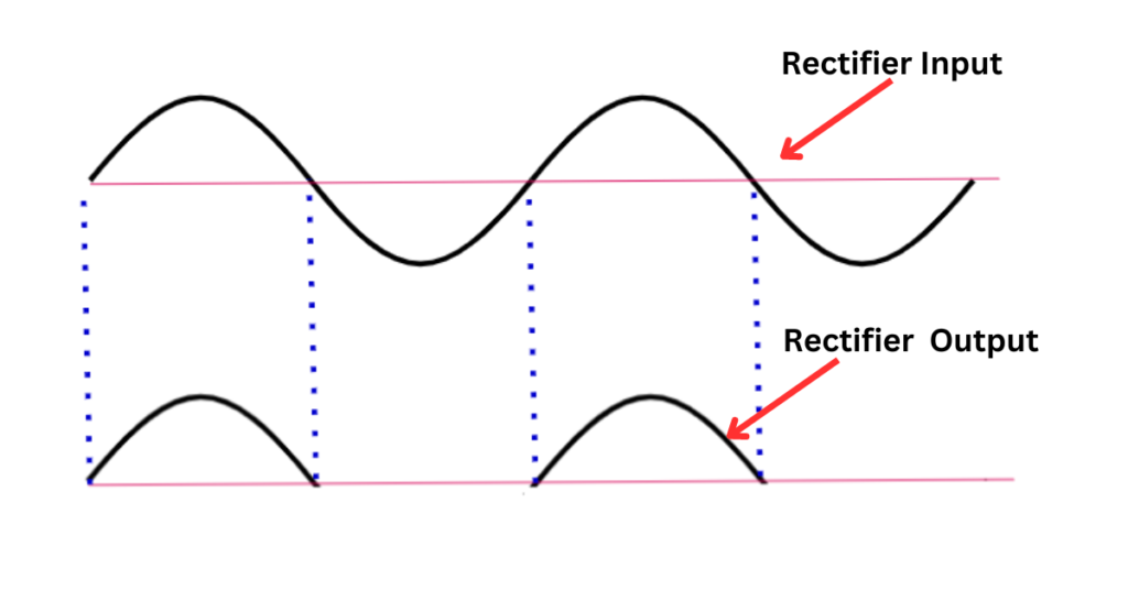
As a result, the output of a half-wave rectifier is a pulsating DC signal consisting of only the positive half-cycles of the AC input. The circuit is simple and easy to implement, but it is less efficient than a full-wave rectifier because only half of the input signal is utilized.
The half-wave rectifier circuit includes the transformer’s primary and secondary windings, a p-n junction diode, and the load resistance RL.
Half Wave Rectifier Circuit
A half-wave rectifier circuit typically consists of the following components.
- Diode: Acts as a gate that only allows electrons to flow in one direction, thereby converting AC into pulsating DC.
- Transformer: Provides voltage transformation to adjust the input voltage to a suitable level for rectification and isolate the circuitry from the power source for safety.
- Load Resistor: Represents the device that uses the output DC power. I
The Half-wave rectifier diagram is given below.
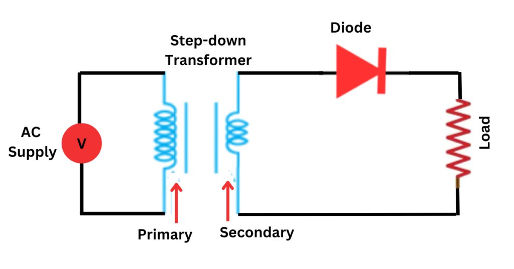
The half-wave rectifier receives an Alternating Current as input. The output voltage is measured using the load resistor RL. As the name suggests, the halfwave rectifier outputs only the positive half-cycle of the input wave. This is achieved due to a p-n junction diode that conducts current only in one direction. As a result, the output pulse only produces output for the positive input cycle.
Working of Half Wave Rectifier
A half-wave rectifier is a circuit that converts alternating current (AC) to direct current (DC). The circuit relies on a diode to selectively allow current to pass only during one-half of the AC cycle.
Flow of Current During Positive and Negative Half-Cycles:
- During Positive Half-Cycles: When the AC supply goes positive, the diode’s anode becomes positive relative to the cathode. If this voltage exceeds the diode’s forward voltage (typically around 0.7 V for silicon diodes), the diode conducts, allowing current to flow through the load resistor. The voltage across the load is approximately the input peak voltage minus the diode’s forward voltage drop.
- During Negative Half-Cycles: When the AC supply is negative, the diode’s anode is at a lower potential than the cathode. The diode is reverse-biased and blocks current, preventing current from flowing through the load resistor. Thus, the voltage across the load is zero during this half-cycle.
- Output Voltage Characteristics: The resulting output voltage is a pulsating direct current. It consists of a series of pulses at the frequency of the input AC waveform, separated by periods of zero voltage during the negative half-cycles. This type of waveform has a relatively high ripple factor, which means the DC output is not smooth.
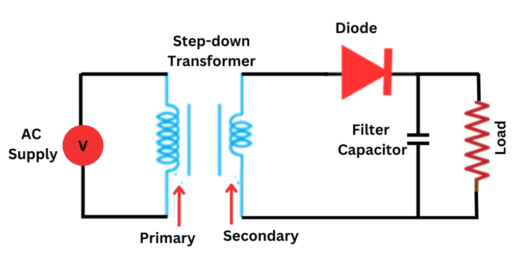
- Filtering (Optional): If smoother DC output is desired, a filter circuit can be added, usually consisting of a capacitor or an inductor. A capacitor placed in parallel with the load helps smooth out the output by charging during the positive half-cycle and discharging when the voltage drops, reducing the ripple.
Half Wave Rectifier Formula
Below are the key formulas related to half wave rectifiers:
1. Peak Output Voltage (Vpeak):
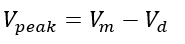
- Where:
- Vm : Peak AC input voltage
- Vd : Diode forward voltage drop (typically around 0.7V for silicon diodes and 0.3V for germanium diodes)
2. The output voltage of a half wave rectifier:
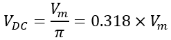
- Where:
- Vm : Peak AC input voltage
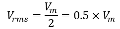
3. Root Mean Square (RMS) Output Voltage (Vrms):
4. Peak Inverse Voltage (PIV):
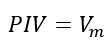
This is the maximum voltage a diode can withstand in reverse-bias mode without breaking down.
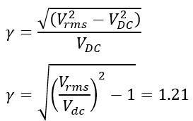
5. Ripple factor of a half wave rectifier:
The ripple factor measures the smoothness of the DC output, representing the amount of AC ripple content present.
6. Efficiency (η):
Efficiency is the ratio of DC power delivered to the load to the AC power input.
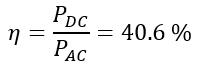
This relatively low efficiency is because only half of the AC waveform is used.
6. Form Factor
The form factor of a half-wave rectifier is the ratio of the root mean square (RMS) value to the average value of the output voltage. This ratio indicates the overall shape of the output waveform.

Application of Half Wave Rectifier
Here are some typical applications:
- Signal Demodulation: Half-wave rectifiers are used in AM radio signal demodulation, where the signal’s envelope (modulation) is detected and extracted as an audio signal.
- Power Supply for Low-Power Devices: They provide a DC supply for low-power electronic devices or circuits where ripple filtering is not critical, such as LED lighting circuits.
- Measuring Instruments: In measuring instruments like voltmeters and ammeters, half-wave rectifiers can convert AC signals to DC signals, simplifying measurement.
- Basic Battery Chargers: They are sometimes used in basic battery charging circuits, particularly for trickle charging, where a low, unregulated DC voltage can suffice.
- Temperature Sensing Circuits: Half-wave rectifiers are used in the sensing/control circuitry for specific temperature-sensing circuits or control systems.
- Signal Conditioning: In some signal processing applications, half-wave rectifiers can condition signals by removing negative cycles.
- Peak Detection Circuits: They are also helpful in peak detection circuits that require only positive half-cycles to analyze the signal peaks.
- LED lighting: The half-wave rectifier is commonly used in LED lighting circuits to rectify the input AC voltage and provide DC voltage to the LEDs.
- Power Supplies: The half-wave rectifier is commonly used in small power supplies to provide low DC voltage for electronic devices.
Disadvantages of Half Wave Rectifier
Here are some of the key drawbacks:
- Low Efficiency: Half-wave rectifiers only utilize one half-cycle of the input AC signal, effectively discarding the other half. This results in low efficiency, with the rectified output containing significantly less power.
- Pulsating DC Output: The output of the half-wave rectifier is a pulsating DC voltage, which may cause issues for electronic devices requiring a steady DC voltage.
- High Ripple Factor: The output voltage is not steady because it is essentially a series of pulses corresponding to each positive half-cycle of the AC input. This results in a high ripple factor, which makes the output unsuitable for sensitive electronic devices without additional filtering.
- Low Average DC Output: The average DC output voltage is much lower than that of a full-wave rectifier for a given input voltage. This limitation makes the halfwave rectifier less useful in applications that require higher DC voltage.
- Transformers Operate Inefficiently: When a transformer is used to step down the input voltage, it does so inefficiently because current only flows during half of the AC waveform.
- Electromagnetic Interference (EMI): Half-wave rectifiers can produce more electromagnetic interference due to the abrupt changes in current flow.
- Limited Load Capacity: The high ripple and low DC output make it unsuitable for loads that require stable and clean DC power.
Conclusion
A half wave rectifier is a circuit that converts alternating current (AC) voltage into direct current (DC) voltage using a single diode. This conversion is done by allowing current to flow in only one direction. During the positive half-cycle of the input AC voltage, the diode conducts, and current flows through the load resistor in the forward direction. However, during the negative half-cycle, the diode becomes reverse-biased and does not conduct. As a result, the output voltage across the load resistor is a pulsating DC voltage that is only present during the positive half-cycles of the input voltage. Despite its usefulness, the halfwave rectifier has several disadvantages. These include low efficiency, pulsating DC output, high ripple factor, and low output voltage. Despite these disadvantages, the halfwave rectifier finds applications in various electronic devices where low DC voltage is required. These devices include battery chargers, power supplies, signal detectors, LED lighting, peak detection, and temperature sensors.
Frequently Asked Questions(FAQs)
Here are some frequently asked questions about half-wave rectifiers:
Q1. What is a half-wave rectifier, and how does it work?
Ans: A half-wave rectifier is a circuit that converts AC (alternating current) to pulsating DC (direct current) by using a single diode. The diode allows current to pass only during the positive half-cycle of the AC waveform, blocking the negative half. As a result, the output is a pulsating DC waveform with a high ripple factor.
Q2. How does a half-wave rectifier differ from a full-wave rectifier?
Ans: A half-wave rectifier uses only one diode and conducts current during one half-cycle of the AC input. In contrast, a full-wave rectifier uses multiple diodes to conduct during both half-cycles of the AC input, providing a more consistent and higher average DC output.
Q3. What are the main applications of a halfwave rectifier?
Ans: Half-wave rectifiers are primarily used in low-power applications where simplicity and cost are prioritized over efficiency. Common uses include signal demodulation, basic battery charging circuits, and providing DC power for low-power electronics.
Q4. Why is the efficiency of a half-wave rectifier low?
Ans: Efficiency is low because the half-wave rectifier uses only half of the AC waveform. During the negative half-cycle, no power is delivered to the load, wasting a significant portion of the input energy.
Q5. How can I reduce the ripple in the output of a half-wave rectifier?
Ans: The ripple can be reduced by adding a filter circuit, usually a capacitor, parallel to the load resistor. The capacitor charges during the positive half-cycle and discharges during the negative half-cycle, smoothing the output voltage.
Q6. What are the typical voltage and current stresses on the diode in a halfwave rectifier?
Ans: The diode must handle the Peak Inverse Voltage (PIV), which is the peak input AC voltage. It also needs to withstand the peak forward current when conducting. The exact values depend on the specific circuit parameters.
Q7. What is the form factor of a half-wave rectifier output?
Ans: The form factor is the ratio of the root mean square (RMS) value of the output voltage to its average (DC) value. For a halfwave rectifier, the form factor is approximately 1.57.
Q8. Can a half-wave rectifier charge a battery?
Ans: Yes, a halfwave rectifier can be used for battery charging in low-current applications. However, due to the high ripple and the low average DC output, the charging will be slower and less efficient.
Q1. What is the efficiency of a half-wave rectifier?
Ans. The efficiency of a halfwave rectifier is relatively low, typically around 40-60%, as only half of the AC input voltage is used.
Q9. Is a half-wave rectifier suitable for use with sensitive electronic equipment?
Ans: No, due to the high ripple content in the output, half-wave rectifiers are not ideal for sensitive electronics unless additional filtering or regulation is implemented to smooth the output voltage.