A Transimpedance Amplifier (TIA) is an operational amplifier-based circuit that converts a small input current into a corresponding output voltage. Its voltage gain, expressed as transimpedance, is primarily set by the feedback resistor, making it useful for accurately converting current signals from devices such as photodiodes and other current-output sensors.
What is a Transimpedance Amplifier?
A Transimpedance Amplifier (TIA) is an electronic circuit that converts an input current into a proportional output voltage. It is therefore also known as a current-to-voltage (I-to-V) converter.
Unlike conventional op-amp circuits that primarily process voltage signals, a transimpedance amplifier is designed to work with current-producing sources. Many sensors, including photodiodes operating in photovoltaic mode, generate a current in response to light or another external stimulus rather than producing a directly usable voltage signal.
The TIA converts this small sensor current into a measurable voltage. Its conversion gain, known as transimpedance gain, is mainly determined by the feedback resistor connected around the op-amp. This makes the circuit particularly useful for accurately processing low-level current signals from sensors and other current-output devices.
Converting Current into a Voltage
The basic principle behind a current-to-voltage converter can be understood from Ohm’s Law. When a current flows through a resistor , it produces a voltage drop across the resistor according to:
This relationship is linear when the resistance remains constant. Therefore, for a fixed resistor value, the voltage developed across the resistor is directly proportional to the current flowing through it. For example, with a resistor, doubling the input current will also double the voltage drop across the resistor.
In general, the relationship can be written as:
provided that remains constant. This is the fundamental principle used to convert an input current into a corresponding voltage.
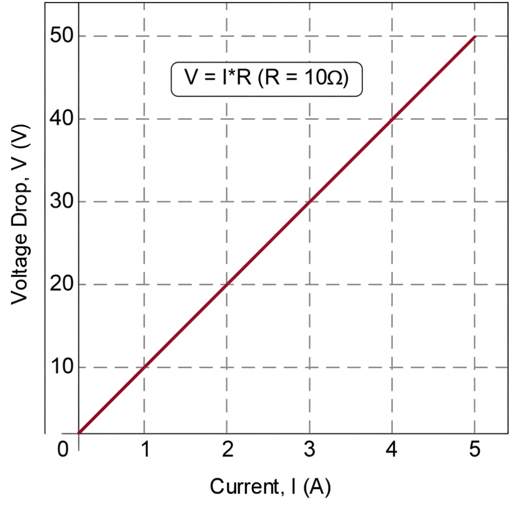
However, using a resistor alone as a current-to-voltage converter has practical limitations. When a relatively large current flows through the resistor, it dissipates power according to:
Excessive power dissipation can cause the resistor to heat up. As its temperature changes, its resistance may also change, causing the voltage-current relationship to deviate from the ideal linear behavior. Consequently, the accuracy of a simple resistor-based current-to-voltage conversion can be affected at higher current levels.
Another limitation is the input impedance created by the resistor. A large resistance may be required to generate a useful voltage from a small current, but this also presents a high impedance to the current source. In many sensor applications, a current-to-voltage converter should instead provide a very low input impedance so that the sensor signal can be transferred with minimal loading.
An operational amplifier provides a better solution. By using an op-amp in an inverting configuration with a feedback resistor, the circuit can convert the input current into a proportional output voltage while providing a low input impedance and a controlled output voltage. This arrangement forms the basic transimpedance amplifier (TIA) or current-to-voltage converter.
Transimpedance Amplifier
A Transimpedance Amplifier (TIA) converts an input current into a corresponding output voltage, allowing a current signal at one point in a circuit to be represented as a voltage signal at another point. Unlike a simple resistor, the TIA provides controlled current-to-voltage conversion without relying on a large voltage drop across the current source.
This raises an important question: How does a transimpedance amplifier perform this conversion, and what advantages does it offer over simply using a fixed resistor?
From an Inverting Amplifier to a Transimpedance Amplifier
A basic Transimpedance Amplifier (TIA) can be formed by configuring an operational amplifier as an inverting amplifier with negative feedback. In this arrangement, the feedback resistor determines the relationship between the input current and the resulting output voltage, thereby setting the circuit’s transimpedance gain.
The input current source is connected to the op-amp’s inverting (−) input, while the feedback resistor is connected between the op-amp output and its inverting input. The non-inverting input is normally connected to ground or a suitable reference voltage.
This configuration converts the input current directly into a proportional output voltage, forming the basic current-to-voltage converter used in a transimpedance amplifier.
Basic Transimpedance Amplifier Circuit
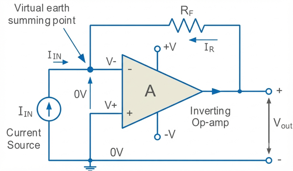
The basic transimpedance amplifier (TIA) uses an operational amplifier in an inverting configuration, but instead of applying an input voltage through an input resistor, the circuit receives an input current directly. The op-amp’s non-inverting input is connected to ground, while a feedback resistor is connected between the output and the inverting input.
The operation of this circuit follows the same fundamental principles as an inverting op-amp. For an ideal op-amp, two important assumptions apply:
- No current flows into either op-amp input terminal.
- The voltage at the inverting input is equal to the voltage at the non-inverting input.
Since the non-inverting input is connected to ground, the inverting input is maintained at approximately 0 V by negative feedback. This condition is known as a virtual ground or virtual earth.
Because the op-amp input draws essentially no current, the entire input current must flow through the feedback resistor. Applying Kirchhoff’s Current Law at the inverting input gives:
Therefore:
The voltage across the feedback resistor is determined by the output voltage and . Since the inverting input is at approximately 0 V,
or,
Combining these relationships gives:
Hence, rearranging for the output voltage:
Transimpedance Amplifier Formula
The negative sign indicates the inverting nature of the circuit. A current flowing into the inverting input produces an output voltage of opposite polarity.
The transimpedance gain is therefore:
Thus, the feedback resistor directly determines the current-to-voltage conversion factor. Increasing produces a larger output voltage for the same input current, while decreasing produces a smaller output voltage.
This simple relationship makes the transimpedance amplifier particularly useful for converting the small current generated by photodiodes and other current-output sensors into a measurable voltage signal.
Choosing a Suitable Feedback Resistor
A transimpedance amplifier (TIA) is essentially a current-to-voltage converter that uses a high-gain amplifier with a feedback resistor. Its transfer relationship is defined as:
Since voltage divided by current has the unit of resistance, the transimpedance gain is expressed in V/A or V/mA. For the basic TIA, the feedback resistor primarily determines this conversion gain:
The negative sign represents the inverting action of the amplifier.
Selecting an appropriate value of is therefore an important part of TIA design. If is too large, even a relatively small input current can produce an output voltage large enough to drive the op-amp into its supply-rail limits. Once the output reaches these limits, the waveform becomes clipped and the amplifier can no longer provide an accurate linear response.
On the other hand, choosing too small produces a relatively low output voltage for a given input current. This can make small variations in the sensor current difficult to detect and may reduce the effective resolution of the measurement system.
Therefore, the feedback resistor should be selected to provide a sufficiently large output signal for the expected range of input current while keeping the output voltage safely within the op-amp’s available output swing.
In its simplest form, the required feedback resistance can be estimated from:
Thus, selecting involves balancing sensitivity and output range: a higher resistance increases sensitivity, while a lower resistance provides greater output-voltage headroom for larger input currents.
Transimpedance Amplifier Worked Example No. 1
Consider a transimpedance amplifier powered by a ±12 V supply and designed to measure input currents up to ±80 µA. Assuming the output voltage should remain within the supply limits, the maximum suitable value of the feedback resistor can be calculated as:
Therefore:
Now, if the input current is 50 µA, the output voltage is:
The negative sign indicates the inverting action of the transimpedance amplifier. With this feedback resistor, an input current greater than approximately 80 µA in magnitude would require an output voltage beyond the assumed ±12 V range, causing the op-amp output to approach saturation and potentially clip.
Transimpedance Amplifier Application: Photodiodes Convert Light into Electrical Current
One of the most common applications of a transimpedance amplifier (TIA) is converting the small current generated by a photodiode into a measurable voltage. This combination is widely used in optoelectronic and light-sensing systems.
A photodiode is a semiconductor device that converts incident light into an electrical current. It is typically based on a p-n junction, with its light-sensitive behavior resulting from the interaction between incoming photons and the semiconductor material.
When photons with sufficient energy strike the photodiode, they generate charge carriers within the semiconductor, producing a photocurrent. The magnitude of this current is related to the amount of incident light, so changes in light intensity produce corresponding changes in photocurrent.
A transimpedance amplifier can then be connected to the photodiode to convert this small photocurrent into a useful output voltage:
where is the photocurrent and is the feedback resistor.
Because the output voltage is proportional to the photodiode current, the TIA provides a convenient way to process the light signal in electronic circuits. This arrangement is commonly used in light meters, optical encoders, optical communication systems, barcode scanners, and other light-detection applications.
A Photodiode Transimpedance Amplifier
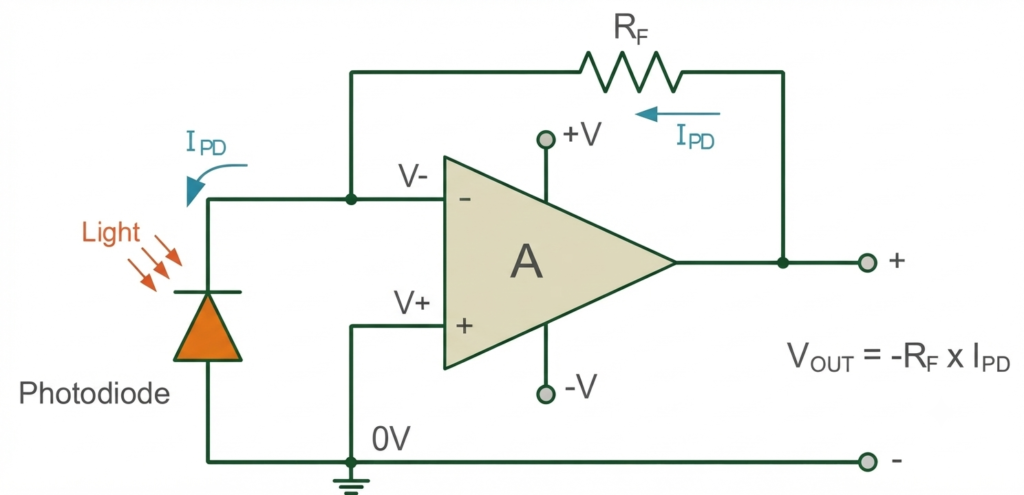
In a photodiode transimpedance amplifier, the photodiode is connected between the op-amp input terminals, with the non-inverting (+) input connected to ground and the anode connected to the inverting input. This arrangement allows the op-amp’s feedback action to maintain the inverting input close to virtual ground.
The photocurrent generated by the photodiode, , flows through the feedback resistor , since the op-amp input draws essentially no current. The feedback resistor therefore converts the small photocurrent directly into an output voltage:
The transimpedance gain is determined primarily by the value of the feedback resistor:
The magnitude of can also be considered the current-to-voltage conversion sensitivity. It specifies how much the output voltage changes for a given change in photocurrent. For example:
- gives a sensitivity of 1 V/mA.
- gives a sensitivity of 1 V/µA.
A higher feedback resistance therefore provides greater sensitivity to small photocurrents, but it also produces a larger output voltage for the same input current. If is too large, the op-amp can reach its output-voltage limit at relatively low photocurrent levels.
For this reason, selecting involves a trade-off between sensitivity and usable input-current range. When the photodiode must operate over a wide range of light levels, multiple feedback resistors can be selected using switches or electronic switching. This allows the transimpedance gain to be changed according to the photocurrent level, providing greater measurement range while maintaining useful output sensitivity.
Adjustable Photodiode Transimpedance Amplifier
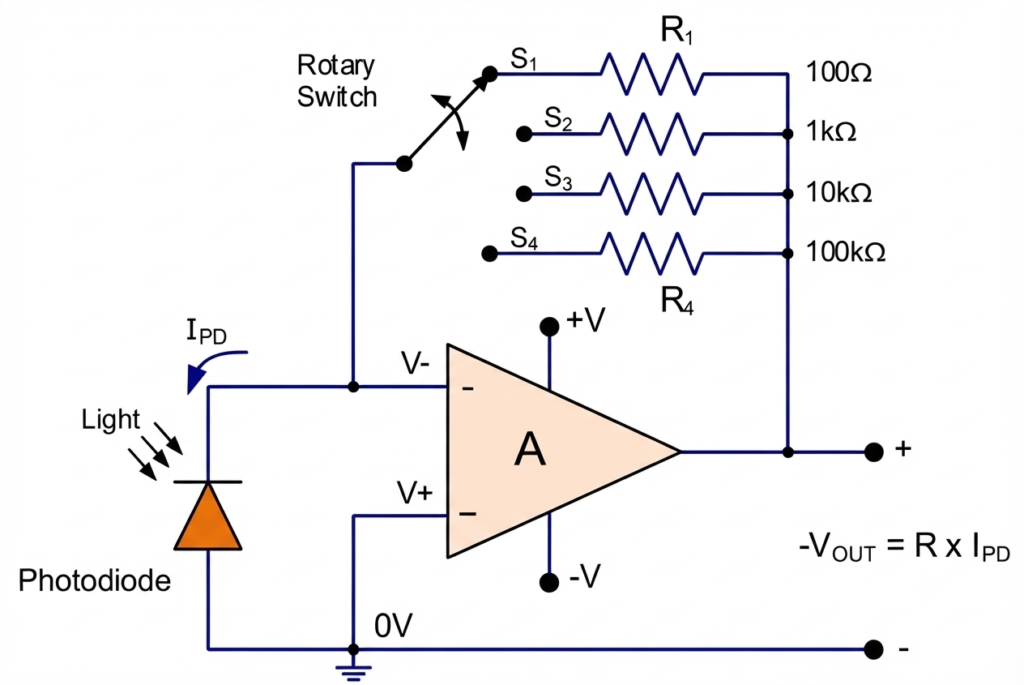
An adjustable photodiode transimpedance amplifier allows the current-to-voltage conversion gain to be changed according to the level of photocurrent being measured. In the example circuit, a four-position rotary switch selects different feedback resistors, providing transimpedance values ranging from 100 Ω in position 1 to 100 kΩ in position 4.
For the same photodiode current, selecting the 100 kΩ feedback resistor produces 1,000 times greater transimpedance gain than selecting the 100 Ω resistor. This provides a practical way to select lower resistance for stronger light signals and higher resistance when greater sensitivity is required for weak signals.
The circuit can be made continuously adjustable by replacing the rotary switch and individual resistors to with a 100 kΩ potentiometer. Adjusting the potentiometer changes the feedback resistance and therefore varies the transimpedance gain, allowing the light sensitivity of the photodiode circuit to be adjusted as required.
Conclusion
A Transimpedance Amplifier (TIA) is a useful op-amp circuit for converting a small input current into a proportional output voltage. Its basic operation relies on a feedback resistor , which determines the current-to-voltage conversion gain:
The choice of is important because a higher resistance increases sensitivity but reduces the maximum input-current range before output saturation. A lower resistance provides a wider current range but produces a smaller output signal.
The TIA is particularly valuable in photodiode applications, where the photocurrent generated by incident light must be converted into a measurable voltage. By using selectable feedback resistors or an adjustable feedback element, the circuit can accommodate different light levels and provide a suitable combination of sensitivity, measurement range, and output voltage.
Overall, transimpedance amplifiers are widely used in photodetection, optical communication, light measurement, optical encoders, and other sensor-interface applications where accurate current-to-voltage conversion is required.
Read Next:
- Inverting vs Non-Inverting Amplifier: Differences, Gain, and Applications
- Inverting Operational Amplifier: Circuit, Working, and Gain Formula
- Op-Amp Building Blocks: Basic Circuits and Applications
- Operational Amplifier (Op-Amp): Basics, Types, Working & Applications
- Non-inverting Operational Amplifier: Circuit, Gain & Formula
- Summing Amplifier: Circuit, Gain Formula, Derivation & Applications
- Differential Amplifier: Circuit, Types, Formula & Applications
- Op-Amp Integrator Amplifier: Formula, Working & Applications
- Op-Amp Differentiator Amplifier: Circuit, Working, Formula & Applications
- Op-Amp Multivibrator: Working, Circuit, Types & Applications
- Op-Amp Comparator: Circuit, Working, Formula, Hysteresis & Applications
- Op-Amp Monostable Multivibrator: Circuit, Working, Formula & Timing
- Passive Averager: Circuit, Equation & Op-Amp Averager
- Instrumentation Amplifier: Circuit, Working. Gain, Applications