The Common-Mode Rejection Ratio (CMRR) of an op-amp is an important parameter that describes how effectively an operational amplifier rejects signals that appear simultaneously at both input terminals. In practical circuits, unwanted signals such as electrical noise, interference, and ground-related disturbances can appear on both inputs. A high-CMRR op-amp can suppress these common-mode signals while accurately amplifying the desired voltage difference between its inputs.
CMRR is particularly important in differential amplifiers, instrumentation amplifiers, sensor interfaces, data-acquisition systems, and measurement circuits, where the useful differential signal may be much smaller than the unwanted common-mode voltage.
What is CMRR of an Op-Amp?
An operational amplifier has two input terminals: the inverting input (−) and the non-inverting input (+). Ideally, the op-amp should respond only to the difference between these two input voltages.
The differential input voltage is:
However, in a practical op-amp, a voltage that is common to both inputs can also produce a small output signal. This voltage is called the common-mode voltage.
The common-mode voltage is defined as:
The ability of an op-amp to reject this common-mode component is specified by its Common-Mode Rejection Ratio (CMRR).
In simple terms, CMRR indicates how much better the amplifier responds to the difference between its inputs compared with a voltage that is present on both inputs.
CMRR Formula of Op-Amp
An op-amp has two important voltage gains:
- = differential voltage gain
- = common-mode voltage gain
The CMRR is defined as:
A higher CMRR means that the op-amp has a greater ability to reject common-mode signals.
Because CMRR can have a very large numerical value, it is normally expressed in decibels (dB):
For example, if:
and
then:
and:
Thus, the CMRR of the amplifier is 100 dB.
Differential Gain and Common-Mode Gain
To understand CMRR more clearly, it is useful to distinguish between differential gain and common-mode gain.
Differential Gain
Differential gain is the gain applied to the voltage difference between the two input terminals:
where:
The desired input signal in a differential measurement system is normally represented by this differential voltage.
Common-Mode Gain
Common-mode gain represents the unwanted response of the amplifier to a voltage that is present on both input terminals:
Ideally:
If the common-mode gain were exactly zero, the amplifier would completely reject any voltage common to both inputs and its CMRR would be infinite.
Real op-amps, however, always have some finite common-mode gain.
Why is CMRR Important in an Op-Amp?
In a practical electronic system, both input wires can pick up the same unwanted interference. For example, electromagnetic interference from power cables can induce a similar voltage on both signal lines.
Suppose a sensor produces a small differential signal of only a few millivolts, while several hundred millivolts of electrical interference appears on both input terminals. An amplifier with poor common-mode rejection may convert part of this unwanted common-mode voltage into an output error.
A high-CMRR amplifier minimizes this error.
This is especially important when:
- The desired signal is very small.
- The input wires are relatively long.
- The signal is transmitted in a noisy industrial environment.
- Sensors are connected through differential wiring.
- Large common-mode voltages are present.
- High measurement accuracy is required.
Therefore, CMRR is an important specification when selecting an op-amp for precision signal conditioning and measurement applications.
CMRR vs Frequency
The CMRR of an op-amp is not necessarily constant over the entire operating frequency range. In practical amplifiers, CMRR generally decreases as frequency increases.
At low frequencies, the internal amplifier circuitry can provide relatively effective rejection of common-mode signals. As frequency increases, internal parasitic capacitances, device limitations, phase differences, and other frequency-dependent effects become increasingly significant.
Typical low-frequency CMRR values for operational amplifiers may range from about 70 dB to 120 dB. As the operating frequency increases, however, the CMRR generally decreases. Along with the specified CMRR value, many op-amp datasheets also provide a CMRR-versus-frequency graph, which illustrates how common-mode rejection changes with frequency, as shown in Figure 1.
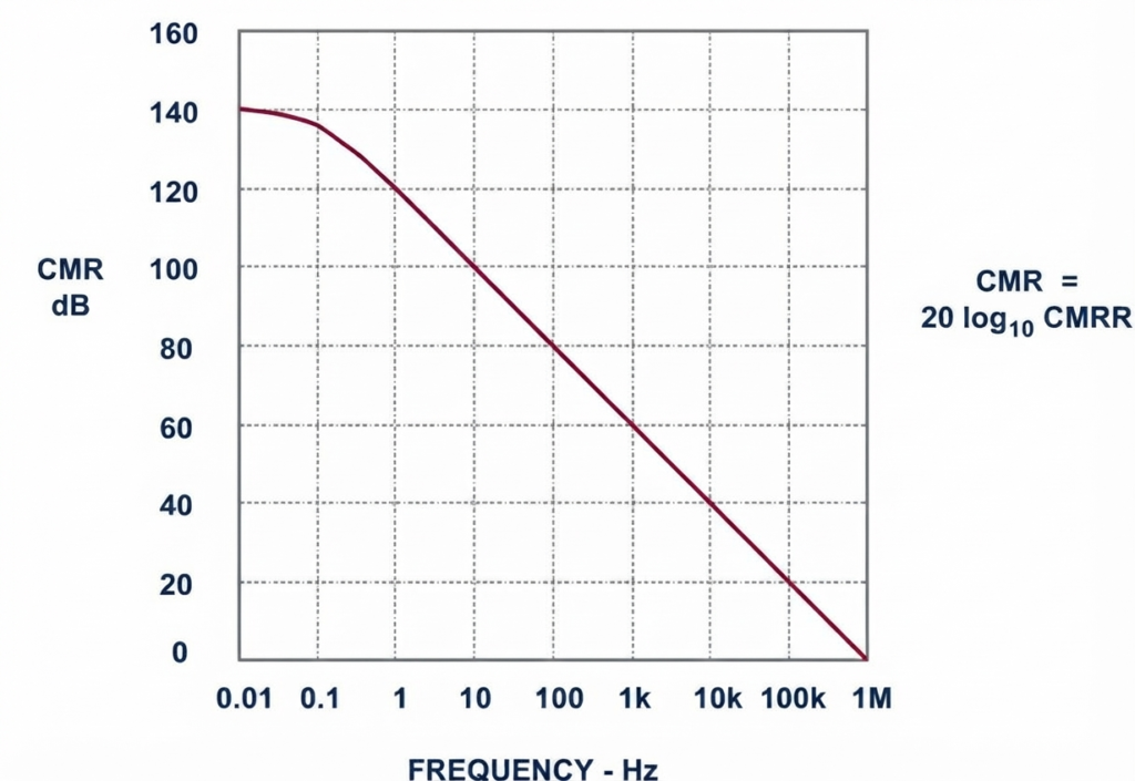
Therefore, an op-amp may have a high CMRR at low frequency but a considerably lower CMRR at higher frequencies.
A typical CMRR-versus-frequency characteristic can therefore be represented as a curve in which:
- CMRR is relatively high at low frequencies.
- CMRR gradually decreases as frequency increases.
- Common-mode rejection becomes less effective at higher frequencies.
For this reason, the CMRR specification should always be considered at the frequency of the actual application, rather than relying only on the maximum or typical CMRR value quoted for low-frequency operation.
How to Measure CMRR of an Op-Amp
CMRR can be determined by measuring the amplifier’s response to differential and common-mode signals.
The basic procedure is to first determine the differential gain and then determine the common-mode gain.
Step 1: Measure Differential Gain
Apply equal and opposite voltages to the two input terminals so that a known differential voltage is produced.
The differential gain is:
where is the output produced by the differential input.
Step 2: Measure Common-Mode Gain
Apply the same voltage simultaneously to both input terminals:
Ideally, this should produce zero output. In a practical amplifier, a small output voltage will appear.
The common-mode gain is:
Step 3: Calculate CMRR
Once both gains are known:
or in decibels:
This provides a practical measurement of the amplifier’s ability to distinguish the desired differential signal from unwanted common-mode signals.
CMRR of a Differential Amplifier
A differential amplifier is specifically designed to amplify the voltage difference between two inputs while rejecting signals common to both.
Its output can be represented generally as:
For an ideal differential amplifier:
and therefore:
In a practical differential amplifier, however, is not exactly zero.
One important factor affecting CMRR is resistor matching. In a resistor-based differential amplifier, even small differences between resistor ratios can cause a common-mode voltage to appear at the output.
For example, the resistor ratios should closely satisfy the required matching condition:
Poor resistor matching reduces common-mode rejection.
This is why precision resistor networks are often used in applications where high CMRR is required.
CMRR of an Instrumentation Amplifier
An instrumentation amplifier is designed specifically for accurate amplification of small differential signals, and high CMRR is one of its important characteristics.
A typical three-op-amp instrumentation amplifier uses:
- Two input buffer amplifiers.
- One differential amplifier.
- A precision resistor network.
- A gain-setting resistor.
The input buffers provide high input impedance, while the differential output stage rejects common-mode signals.
The overall performance depends on several factors, including:
- Op-amp CMRR.
- Resistor matching.
- Gain setting.
- Frequency.
- Temperature.
- Common-mode voltage.
- PCB layout and external interference.
In precision instrumentation amplifiers, resistor matching is particularly important because even a small mismatch can convert part of the common-mode voltage into an unwanted differential output error.
For sensor applications, a high-CMRR instrumentation amplifier can therefore be used to extract a small sensor signal even when both sensor leads carry a much larger common-mode voltage.
CMRR of an Ideal Op-Amp
An ideal op-amp is assumed to reject common-mode signals completely.
For an ideal op-amp:
Therefore:
which theoretically gives:
In other words, an ideal op-amp responds only to the differential voltage between its two inputs and completely ignores any voltage that is common to both.
Real op-amps cannot achieve infinite CMRR. Their finite CMRR results from limitations in the internal transistor circuitry, component matching, frequency response, temperature variation, and other non-ideal effects.
CMRR and Common-Mode Voltage Example
Consider an amplifier with a differential gain of:
and a common-mode gain of:
The CMRR is:
In decibels:
This means the amplifier provides a much larger gain for the differential component than for the common-mode component.
Factors That Affect Op-Amp CMRR
Several factors can influence the actual CMRR obtained in a circuit.
1. Resistor Matching
In differential amplifier circuits, mismatched resistor ratios can convert common-mode voltage into an unwanted output voltage. Precision resistors or integrated resistor networks can improve matching.
2. Frequency
CMRR generally decreases as operating frequency increases. Therefore, the CMRR at the signal frequency is more relevant than the low-frequency specification alone.
3. Temperature
Changes in temperature can alter the characteristics of the internal components and external resistors, potentially reducing common-mode rejection.
4. Common-Mode Voltage
An op-amp has a specified common-mode input voltage range. Operating outside the recommended range can cause incorrect operation and degrade signal accuracy.
5. PCB Layout
Poor circuit layout can introduce unwanted coupling and noise. Careful grounding, short signal paths, appropriate shielding, and differential routing can help preserve the practical common-mode rejection of the circuit.
6. Gain Configuration
The closed-loop configuration and gain of an op-amp circuit can influence the effective common-mode rejection observed at the system level.
CMRR vs Differential Gain
CMRR and differential gain describe different aspects of amplifier performance.
| Parameter | Meaning | Desired characteristic |
Differential Gain AD | Amplification of the voltage difference between inputs | High, depending on application |
Common-Mode Gain ACM | Amplification of a voltage common to both inputs | Very low |
| CMRR | Ratio of differential gain to common-mode gain | High |
| CMRR in dB | Logarithmic representation of CMRR | Higher value indicates better rejection |
The important point is that high differential gain alone does not guarantee good common-mode rejection. An amplifier must also have a very low common-mode gain to achieve a high CMRR.
Applications of High-CMRR Amplifiers
High CMRR is particularly useful in circuits where the desired signal is small compared with unwanted common-mode interference.
Typical applications include:
- Strain-gauge measurement
- Load-cell amplifiers
- Thermocouple signal conditioning
- Pressure and temperature sensors
- Biomedical instrumentation
- Industrial data acquisition
- Current and voltage measurement
- Bridge measurement circuits
- Instrumentation amplifiers
- Remote sensor interfaces
- Industrial process-control systems
For example, a strain gauge may produce a differential signal of only a few millivolts while electrical interference is coupled onto both signal wires. A high-CMRR instrumentation amplifier can significantly reduce the effect of this common-mode interference before the signal is passed to an ADC or control system.
CMRR in Practical Op-Amp Circuits
It is important to remember that the CMRR specified in an op-amp datasheet represents the device’s performance under particular test conditions. The CMRR of the complete circuit can be different because external resistor tolerances, layout, temperature, frequency, and common-mode voltage also contribute to the overall error.
For precision applications, therefore, CMRR should be considered as part of the complete signal-conditioning design, rather than as an isolated op-amp specification.
Conclusion
The Common-Mode Rejection Ratio (CMRR) of an op-amp indicates how effectively the amplifier rejects signals that are common to both input terminals while amplifying their voltage difference. It is defined as the ratio of differential gain to common-mode gain:
and is commonly expressed in decibels:
A high CMRR is particularly important in differential amplifiers and instrumentation amplifiers, where small measurement signals may exist alongside much larger common-mode interference. In practical circuits, CMRR is affected by resistor matching, frequency, temperature, common-mode voltage, op-amp characteristics, and PCB layout, so all of these factors should be considered when designing a precision measurement system.
Read Next:
- Inverting vs Non-Inverting Amplifier: Differences, Gain, and Applications
- Inverting Operational Amplifier: Circuit, Working, and Gain Formula
- Op-Amp Building Blocks: Basic Circuits and Applications
- Operational Amplifier (Op-Amp): Basics, Types, Working & Applications
- Non-inverting Operational Amplifier: Circuit, Gain & Formula
- Summing Amplifier: Circuit, Gain Formula, Derivation & Applications
- Differential Amplifier: Circuit, Types, Formula & Applications
- Op-Amp Integrator Amplifier: Formula, Working & Applications
- Op-Amp Differentiator Amplifier: Circuit, Working, Formula & Applications
- Op-Amp Multivibrator: Working, Circuit, Types & Applications
- Op-Amp Comparator: Circuit, Working, Formula, Hysteresis & Applications
- Op-Amp Monostable Multivibrator: Circuit, Working, Formula & Timing
- Passive Averager: Circuit, Equation & Op-Amp Averager
- Instrumentation Amplifier: Circuit, Working. Gain, Applications
- Transimpedance Amplifier: Circuit, Formula & Applications
- Slew Rate: Definition, Formula, Unit, Calculation, Measurement & Applications