An ideal diode is a theoretical or conceptual model used in electronics to simplify the analysis and design of electronic circuits. This model represents a diode that operates with perfect efficiency and zero imperfections, which is helpful for understanding the basic function of diodes.
What is an Ideal Diode?
In its simplest form, an ideal diode is a two-terminal semiconductor device that allows current to flow in only one direction. It behaves as a perfect conductor when forward-biased and as a perfect insulator when reverse-biased. An ideal diode has no threshold voltage, meaning it begins to conduct as soon as a forward voltage is applied, and it has no reverse leakage current.
Characteristics of an Ideal Diode
1. Forward Bias Condition:
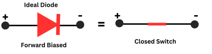
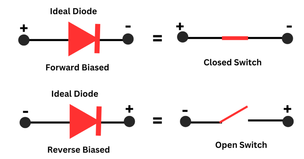
- Zero Voltage Drop: When forward biased (positive voltage on the anode relative to the cathode), an ideal diode conducts current instantly without any voltage drop across it. Unlike real diodes, which typically have a forward voltage drop (usually around 0.7V for silicon diodes).
- Zero Resistance: An ideal diode or a perfect diode behaves as a perfect conductor when it is forward-biased, offering no resistance to the flow of current. This property leads to the inference that a perfect diode does not have barrier potential. Consequently, one may question whether an perfect diode possesses a depletion region, as the resistance offered by a diode is due to the presence of immobile charges in the depletion region.
2. Reverse Bias Condition:
- Infinite Resistance: In reverse bias (positive voltage on the cathode relative to the anode), the ideal diode does not conduct any current, effectively behaving as an open circuit. There is no leakage current, which contrasts with real diodes, which usually have a small, albeit negligible, reverse saturation current.
- Zero Reverse Leakage Current: The perfect diode has infinite resistance, therefore the current through it in reverse bias is zero. (I=V/R=V/∞=0)
- No Reverse Breakdown Voltage: The reverse breakdown voltage is the voltage that causes a reverse-biased diode to fail and start conducting heavy currents. In the case of a perfect diode, it offers infinite resistance, preventing current flow through it, regardless of the magnitude of the reverse voltage applied. As a result, the phenomenon of reverse breakdown will never occur, and the corresponding voltage, reverse breakdown voltage, will not exist. Due to these properties, an ideal diode behaves as a perfect semiconductor switch, which remains open when reverse-biased and closed when forward-biased.
VI Characteristics of an Ideal Diode
The VI (voltage-current) characteristics of an ideal diode can be illustrated graphically. In this representation, the current versus voltage curve sharply transitions from zero current in reverse bias to a vertical line, indicating infinite current capability in forward bias at zero voltage. This characteristic is often depicted as a right angle forming along the axes of a VI graph:
- X-axis (Voltage): Negative values represent reverse bias, and positive values represent forward bias.
- Y-axis (Current): Positive values indicate the flow of current.
The following figure displays the V-I characteristics of an Ideal diode.
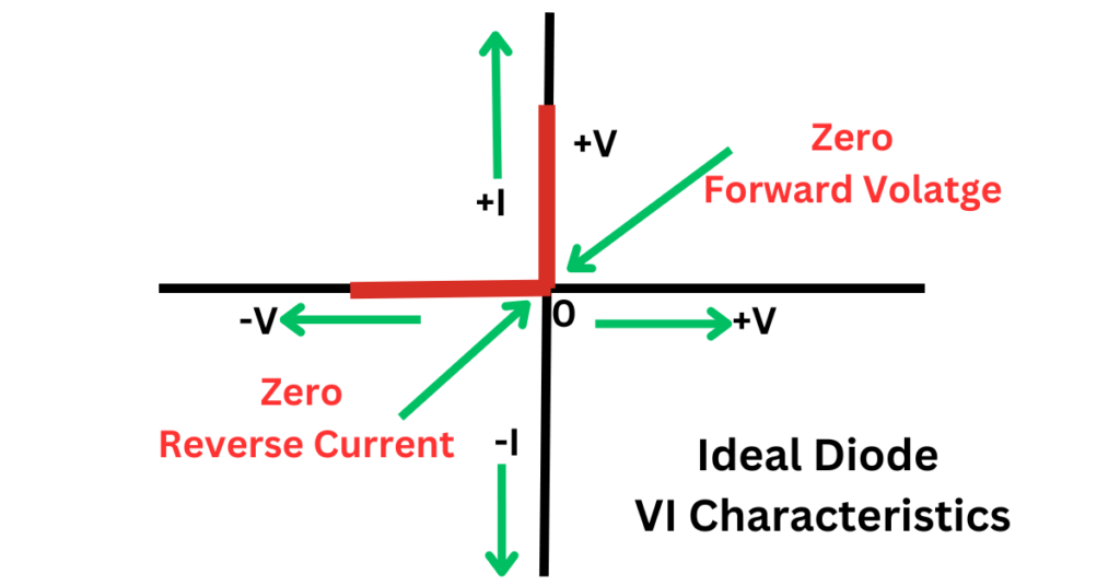
The resulting graph is divided into two distinct regions:
- Reverse Bias Region: The line lies flat along the voltage axis, indicating zero current regardless of the negative voltage applied.
- Forward Bias Region: The line shoots vertically upwards from the origin, showing that any positive voltage leads to an immediate and unrestricted flow of current.
Practical Relevance and Limitations
While no real diode can achieve the ideal characteristics due to physical limitations and material properties, the ideal diode model is crucial in educational settings and preliminary circuit design. It helps in understanding the basic principles of diode operation, making it easier to grasp how diodes influence the behavior of electronic circuits.
In practical applications, engineers use models like the Shockley diode equation to more accurately predict diode behavior, which accounts for the forward voltage drop and reverse saturation current. Advanced simulations and designs require considering non-ideal behaviors such as junction capacitance, reverse recovery time, and breakdown voltage, none of which are factors in the perfect diode model.
Conclusion
In summary, the ideal diode concept serves as an educational and theoretical tool in electronics, offering a simplified model that helps demystify how diodes control the direction of current flow in circuits. Understanding this ideal model provides a foundation for exploring more complex and realistic semiconductor devices.