Every diode has a diode voltage drop when it conducts current. This voltage loss affects how much voltage reaches the load, how much power the diode dissipates as heat, and whether a low-voltage circuit can operate properly.
This guide explains the typical diode voltage drop for different diode types, the formula used to calculate it, the factors that affect it, how to measure it with a multimeter, and why it is important in practical electronic circuits.
What Is Diode Voltage Drop?
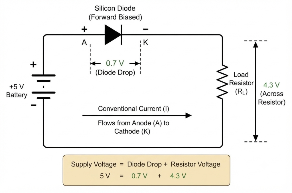
Diode voltage drop is the voltage that appears across a diode when it conducts current in the forward direction. It is commonly represented by and is also known as forward voltage or forward voltage drop.
When a diode is forward biased, current flows from the anode to the cathode, and a voltage develops across the semiconductor junction. The value of this diode voltage drop is not constant. It varies with the diode type, forward current, temperature, and semiconductor construction.
An ideal diode has a 0 V voltage drop and behaves like a perfect closed switch when forward biased. A real diode, however, has a measurable forward voltage because the semiconductor junction requires a certain voltage for significant current to flow. This voltage loss also causes power dissipation in the form of heat.
Therefore, the diode voltage drop is an important parameter when designing and analyzing electronic circuits because it determines how much of the available supply voltage is delivered to the load.
Diode Voltage Drop Chart by Diode Type
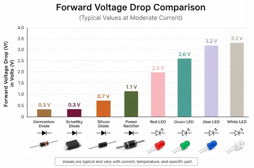
The diode voltage drop varies significantly depending on the diode’s semiconductor material, construction, and operating current. Standard silicon diodes generally have a higher forward voltage than germanium and Schottky diodes, while LEDs require a higher forward voltage because they convert electrical energy into light.
The values below provide typical ranges for quick reference. Actual forward voltage can vary with forward current, junction temperature, manufacturing tolerances, and the specific part number, so the manufacturer’s datasheet should always be checked for accurate design values.
| Diode Type | Typical Diode Voltage Drop (Vf) | Common Use |
| Germanium diode | 0.25–0.30 V | Low-voltage and signal detection circuits |
| Schottky diode | 0.15–0.45 V | Switching, rectification, power supplies |
| Silicon signal diode | 0.55–0.75 V | Switching and general-purpose circuits |
| Silicon PN diode | 0.60–0.80 V | Rectification and protection |
| Power rectifier diode | 0.80–1.20 V | AC-to-DC power conversion |
| Fast-recovery diode | 0.70–1.20 V | High-frequency rectification |
| Zener diode | 0.60–1.00 V | Forward conduction; voltage regulation in reverse bias |
| Red LED | 1.8–2.2 V | Indicators and displays |
| Yellow LED | 2.0–2.4 V | Indicators and lighting |
| Green LED | 2.0–3.2 V | Indicators and displays |
| Orange LED | 2.0–2.4 V | Indicators and displays |
| Blue LED | 2.8–3.8 V | Displays and lighting |
| White LED | 3.0–3.6 V | General lighting and displays |
| Infrared LED | 1.1–1.5 V | Remote controls and optical sensors |
The forward voltage shown for a Zener diode applies when it is forward biased. Its specified Zener voltage applies when the device operates in reverse breakdown.
Why Does the Diode Voltage Drop Vary?
The diode voltage drop is not a fixed value for every operating condition. Several factors can change the voltage measured across the diode:
- Diode material: Silicon, germanium, and Schottky junctions have different forward-voltage characteristics.
- Forward current: As the current increases, the forward voltage generally increases.
- Temperature: For most PN junction diodes, forward voltage decreases as junction temperature rises.
- Diode construction: The internal semiconductor structure affects the forward-voltage characteristic.
- Device rating: Power and high-current diodes can have different forward-voltage values from small-signal devices.
- LED wavelength: Different LED colors use different semiconductor materials, resulting in different forward-voltage ranges.
Example of Diode Voltage Drop
Suppose a silicon diode has a forward voltage of 0.7 V and is connected to a 12 V supply. If the diode is conducting, the approximate voltage available to the rest of the series circuit is:
Therefore, approximately 11.3 V remains for the load, assuming the circuit contains only this series diode and the current is within the diode’s specified operating range.
For this reason, checking the diode voltage drop is important when selecting components for low-voltage circuits, rectifiers, protection circuits, and LED applications.
Diode Voltage Drop by Diode Type
The diode voltage drop depends on the diode’s construction, semiconductor material, and operating conditions. Different diode types are designed for different applications, so their forward-voltage characteristics can vary considerably.
1. Diode Voltage Drop of a Silicon Diode
Silicon diodes are among the most widely used diode types in electronic circuits. A typical silicon diode has a diode voltage drop of about 0.6–0.8 V under normal forward-current conditions. For basic circuit calculations, 0.7 V is commonly used as an approximate value.
The actual forward voltage increases with forward current and varies between individual devices. Power rectifier diodes can have a higher forward voltage when operating near their rated current.
Examples:
- 1N4148: typically around 0.6–0.9 V, depending on forward current
- 1N4007: approximately 0.7–1.1 V over commonly used current ranges
2. Schottky Diode Voltage Drop
A Schottky diode is constructed using a metal-semiconductor junction rather than the conventional PN junction used in standard silicon diodes. This construction generally produces a lower forward voltage and faster switching performance.
A typical Schottky diode voltage drop is approximately 0.15–0.45 V, depending on the device and operating current. The lower forward voltage can reduce conduction losses, making Schottky diodes useful in switching power supplies, DC-DC converters, reverse-polarity protection, and low-voltage rectification.
The main tradeoff is that Schottky diodes generally have higher reverse leakage current than conventional PN junction diodes.
Examples: 1N5817, 1N5819, and SS14.
3. Germanium Diode Voltage Drop
Germanium diodes have a relatively low forward voltage compared with conventional silicon diodes. Their diode voltage drop is typically around 0.25–0.30 V under suitable operating conditions.
This low forward voltage makes germanium diodes useful in low-level signal detection and certain radio-frequency applications. They are particularly associated with crystal radio receivers and signal-detection circuits.
Example: 1N34A germanium diode.
4. LED Voltage Drop
An LED is a semiconductor diode that emits light when it is forward biased. Its diode voltage drop is generally higher than that of standard silicon and germanium diodes.
The forward voltage of an LED depends strongly on the semiconductor material and the wavelength of the emitted light. As a general guide:
- Red LED: about 1.8–2.2 V
- Yellow LED: about 2.0–2.4 V
- Green LED: about 2.0–3.2 V
- Blue LED: about 2.8–3.8 V
- White LED: about 3.0–3.6 V
The actual LED forward voltage should be taken from the manufacturer’s datasheet because it also changes with forward current and temperature.
5. Zener Diode Voltage Drop
A Zener diode can operate in both forward and reverse bias, so its voltage must be considered according to its operating mode.
When forward biased, a Zener diode behaves much like a conventional silicon diode and typically has a forward voltage of around 0.7 V. However, its primary purpose is usually reverse-bias operation, where it conducts when the reverse voltage reaches its specified Zener voltage (Vz).
It is important not to confuse forward voltage (Vf) with Zener voltage (Vz). Vf describes the diode’s forward conduction, while Vz refers to its specified reverse-breakdown voltage.
6. Fast-Recovery Diode Voltage Drop
A fast-recovery diode is designed to switch from the conducting state to the blocking state quickly. Its forward-voltage characteristic is generally similar to that of a conventional silicon PN diode, although the exact diode voltage drop depends on the specific device and operating current.
These diodes are commonly used in switch-mode power supplies, high-frequency rectifiers, inverter circuits, and other high-speed power-electronic applications.
When selecting a fast-recovery diode, forward voltage is only one consideration. Reverse-recovery time, maximum repetitive reverse voltage, forward current, and power dissipation are also important parameters.
Why Do Diodes Have a Voltage Drop?
A diode voltage drop occurs because a real semiconductor diode does not behave like an ideal switch. Its internal PN junction has electrical properties that require a certain forward voltage before substantial current can flow. The value of this voltage depends on the diode material, current, temperature, and device construction.
The PN Junction Barrier
A PN junction is formed when P-type and N-type semiconductor materials are joined together. When the junction is formed, electrons and holes diffuse across the boundary and recombine near the junction. This process creates a depletion region containing very few mobile charge carriers.
An internal electric field develops across this depletion region, creating a built-in potential barrier. When the diode is forward biased, the applied voltage reduces the effect of this barrier and allows charge carriers to cross the junction more easily.
As forward current increases, a measurable voltage develops across the diode. This voltage is the forward voltage (Vf), commonly referred to as the diode voltage drop.
Why Is a Silicon Diode Often Called a 0.7 V Diode?
A silicon diode is often approximated as having a 0.7 V diode voltage drop in basic circuit calculations. This value represents a convenient engineering approximation for a typical silicon PN junction operating at a moderate forward current.
However, 0.7 V is not a fixed voltage or a universal threshold. A silicon diode can have a forward voltage below or above 0.7 V depending on its forward current, junction temperature, and specific construction.
For example, a small-signal diode may have a forward voltage of approximately 0.6–0.7 V at one current level and a higher value when the current increases. Therefore, the manufacturer’s datasheet should be used when an accurate voltage value is required.
Why Is Diode Forward Voltage (Vf) Not Fixed?
The forward voltage of a real diode does not suddenly switch from 0 V to 0.7 V. Instead, the relationship between forward voltage and current follows a nonlinear, approximately exponential I–V characteristic.
At very low forward voltages, a small current can already flow through the diode. As the forward voltage increases, the current rises rapidly. This is why the commonly quoted 0.7 V diode voltage drop should be treated as a practical approximation rather than a strict turn-on voltage.
The forward voltage also changes with operating conditions. In particular:
- Forward current: Increasing current generally increases .
- Temperature: For a typical silicon PN diode, generally decreases as junction temperature rises.
- Semiconductor material: Different materials produce different forward-voltage characteristics.
- Diode construction: Device design and junction characteristics affect the actual .
Therefore, when calculating a real circuit, it is better to consider the diode voltage drop at the actual operating current and temperature rather than simply assuming a fixed 0.7 V value.
Factors Affecting Diode Voltage Drop
The diode voltage drop is not a fixed value. It changes with operating conditions and the physical characteristics of the device. The most important factors are forward current, temperature, semiconductor material, and diode construction.
1. Forward Current
The diode voltage drop increases as forward current increases. This behavior follows the diode’s nonlinear I–V characteristic. Over a practical operating range, the forward voltage changes approximately logarithmically with current.
For example, the same silicon diode may have a much lower forward voltage at a few milliamps than it does when carrying several amperes. Therefore, using a single value such as 0.7 V for every operating condition can lead to inaccurate calculations.
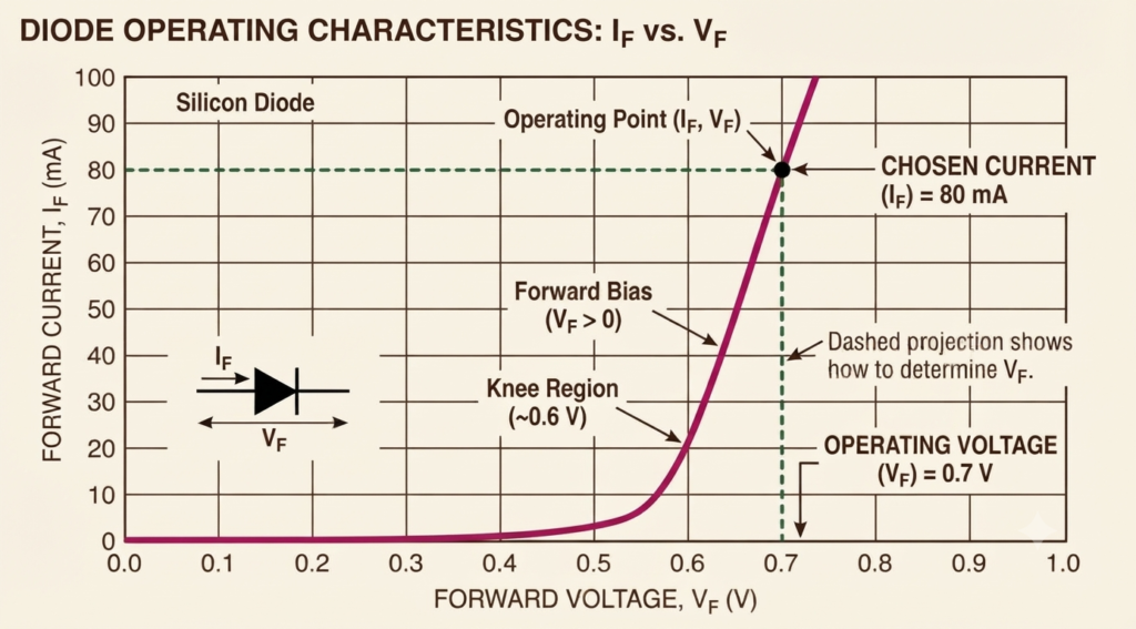
Figure: Silicon diode I–V characteristic showing the increase in forward voltage as forward current increases.
For power applications, the manufacturer’s datasheet should be checked for the specified forward voltage at the expected operating current.
2. Diode Temperature
Temperature also has a significant effect on the diode voltage drop. For a typical silicon PN diode operating at a given current, the forward voltage generally decreases as junction temperature increases. A commonly used approximation is around −2 mV/°C, although the actual temperature coefficient varies with the diode and operating point.
For example, if a diode has a forward voltage of 0.70 V at a particular current and its junction temperature increases, its forward voltage may decrease.
This temperature dependence is particularly important in high-current circuits. A reduction in forward voltage can increase current in some circuit configurations, causing additional power dissipation and further heating. If the circuit does not provide adequate current limiting or thermal control, this positive feedback can contribute to thermal runaway.
3. Semiconductor Material
The semiconductor material and junction technology strongly influence the typical diode voltage drop.
| Diode Type | Typical Forward Voltage |
|---|---|
| Silicon PN diode | ~0.6–0.8 V |
| Germanium diode | ~0.25–0.30 V |
| Schottky diode | ~0.15–0.45 V |
These values are only typical ranges. The actual forward voltage depends on the device, forward current, and temperature.
4. Diode Construction and Device Structure
The physical construction of a diode also affects its forward-voltage characteristics. Different devices are optimized for different current levels, switching speeds, voltage ratings, and applications.
- Signal diodes: Designed for relatively small currents and fast response. Their forward voltage depends on the specific device and operating current.
- Power rectifier diodes: Designed to handle higher currents and dissipate more heat. Their forward voltage must be considered at the intended load current.
- High-current diodes: May have significant forward-voltage losses when operated near their rated current, making conduction loss and thermal management important.
For a power diode, even a relatively small increase in forward voltage can produce substantial additional power loss because the conduction loss is approximately:
where:
- = diode power dissipation in watts (W)
- = forward voltage in volts (V)
- = forward current in amperes (A)
For example, a diode with a 1.0 V diode voltage drop carrying 5 A dissipates approximately:
This illustrates why the diode voltage drop is an important parameter when selecting components for high-current rectifiers and power-electronic circuits.
How to Calculate Diode Voltage Drop
The diode voltage drop can be estimated in several ways, depending on how much accuracy is required. For simple circuit calculations, a typical forward-voltage value is usually sufficient. For detailed analysis, the Shockley diode equation or the manufacturer’s datasheet can be used.
Method 1: Quick Engineering Approximation
For basic hand calculations, a diode can be represented by an approximate constant forward voltage. Subtract this voltage from the applied supply to estimate the voltage remaining for the load.
| Diode Type | Typical Approximation |
| Silicon PN diode | 0.7 V |
| Schottky diode | 0.3 V |
| Germanium diode | 0.3 V |
| LED | Use datasheet value |
These values are only approximations. The actual diode voltage drop changes with forward current, temperature, and the particular device.
Example:
Suppose a 5 V supply is connected to a load through a silicon diode. Using an approximate forward voltage of 0.7 V:
Therefore, approximately 4.3 V is available to the load, assuming the diode is the only significant voltage drop in the series path.
Method 2: Using the Shockley Diode Equation
For theoretical analysis of a PN junction, the Shockley diode equation describes the relationship between diode current and forward voltage:
where:
- = diode current in amperes (A)
- = reverse saturation current in amperes (A)
- = voltage across the diode in volts (V)
- = ideality factor, typically between 1 and 2
- = thermal voltage in volts (V)
At approximately 25°C, the thermal voltage is about:
The equation shows that diode current increases very rapidly as forward voltage increases. It also demonstrates why the diode voltage drop is not a fixed value.
For a known current, the equation can also be rearranged to estimate the forward voltage:
The Shockley equation is useful for understanding diode behavior, but practical diode characteristics can differ from this idealized model.
Method 3: Using the Diode Datasheet
For an actual component, the manufacturer’s datasheet is normally the best practical source for determining the diode voltage drop at a particular operating condition.
Follow these steps:
- Identify the exact diode part number.
- Open the manufacturer’s datasheet.
- Find the forward voltage () versus forward current () graph or specification table.
- Locate your expected operating current on the graph.
- Read the corresponding value.
- Check the specified temperature or temperature coefficient if the circuit operates over a wide temperature range.
For example, if the datasheet specifies a forward voltage of 1.0 V at the expected operating current, using 0.7 V as a generic silicon-diode approximation would introduce a significant error.
Case Study: 1N4007 vs. 1N5819 Datasheet Values
Real parts give concrete numbers instead of round approximations:
- 1N4007:
- 1N5819: Vf ≈
Forward-voltage specifications around 1.1V at 1A are common in 1N4007 datasheets. Same current, very different drop, because the 1N5819 is a Schottky.
Which Method Should You Use?
The appropriate method depends on the application:
| Application | Recommended Method |
| Basic circuit calculation | Typical Vf approximation |
| Educational calculations | Typical Vf approximation |
| Understanding diode behavior | Shockley equation |
| Component selection | Manufacturer’s datasheet |
| Power electronics | Datasheet Vf at rated/actual current |
| Precision circuit design | Datasheet curves and temperature data |
For most practical designs, use the typical approximation for an initial calculation and the manufacturer’s datasheet for the final design. This is especially important for power diodes, LEDs, Schottky diodes, and low-voltage circuits where even a small change in forward voltage can significantly affect circuit performance.
How to Measure Diode Voltage Drop With a Multimeter
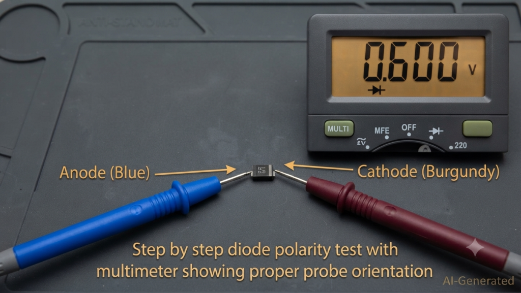
A digital multimeter can be used to measure the diode voltage drop of a diode directly. The diode-test function applies a small test current through the device and displays the resulting forward voltage.
Safety Before Testing
Always switch off the circuit and discharge any capacitors before testing a diode. Measuring a diode in a powered circuit can produce incorrect readings and may damage the multimeter or circuit.
For the most reliable measurement, especially when the diode is installed on a circuit board, isolate at least one diode lead from the circuit. Other components connected in parallel can otherwise affect the reading.
Steps to Measure Diode Voltage Drop
- Turn off the circuit power.
- Discharge all capacitors in the circuit.
- Set the multimeter to diode-test mode.
- Identify the diode’s anode and cathode.
- Connect the red probe to the anode.
- Connect the black probe to the cathode.
- Read the displayed forward voltage ().
- Reverse the probes and check the display. A normally functioning diode should typically show OL or an equivalent open-circuit indication in reverse bias.
In forward bias, the meter displays the diode’s voltage at the test current supplied by the meter. Because this test current is usually much lower than the operating current of a power circuit, the measured value may differ from the forward voltage specified in the component’s datasheet.
Typical Multimeter Readings
| Diode Type | Typical Multimeter Reading |
| Silicon PN diode | 0.5–0.8 V |
| Schottky diode | 0.15–0.45 V |
| Germanium diode | 0.2–0.4 V |
| LED | 1.5–3.5 V |
These values are only general guidelines. The actual diode voltage drop displayed by a multimeter depends on the specific device, the meter’s test current, and the diode’s temperature.
How to Interpret the Reading
A healthy diode normally conducts in one direction and blocks current in the other.
- Normal diode: A forward-voltage reading in one direction and OL in the reverse direction.
- Shorted diode: A very low voltage reading in both directions.
- Open diode: OL or no conduction in both directions.
- Abnormal reading: A significantly different value from the expected range may indicate a faulty diode or an in-circuit measurement affected by other components.
Figure: Digital multimeter in diode-test mode measuring a diode with the probes connected in forward bias.
Important: Multimeter Reading vs. Operating Voltage
The diode voltage drop measured with a multimeter is not necessarily the same as the voltage drop during normal circuit operation. A multimeter uses its own specified test current, while the actual circuit may operate the diode at a much higher or lower current.
For power-electronic applications, use the manufacturer’s Vf versus If datasheet curve to determine the expected diode voltage drop at the actual operating current.
Effect of Diode Voltage Drop on Rectifier Efficiency
The diode voltage drop directly affects the output voltage, power loss, and efficiency of a rectifier. Every time current flows through a conducting diode, part of the available electrical voltage is lost across the diode. This loss becomes heat and reduces the power delivered to the load.
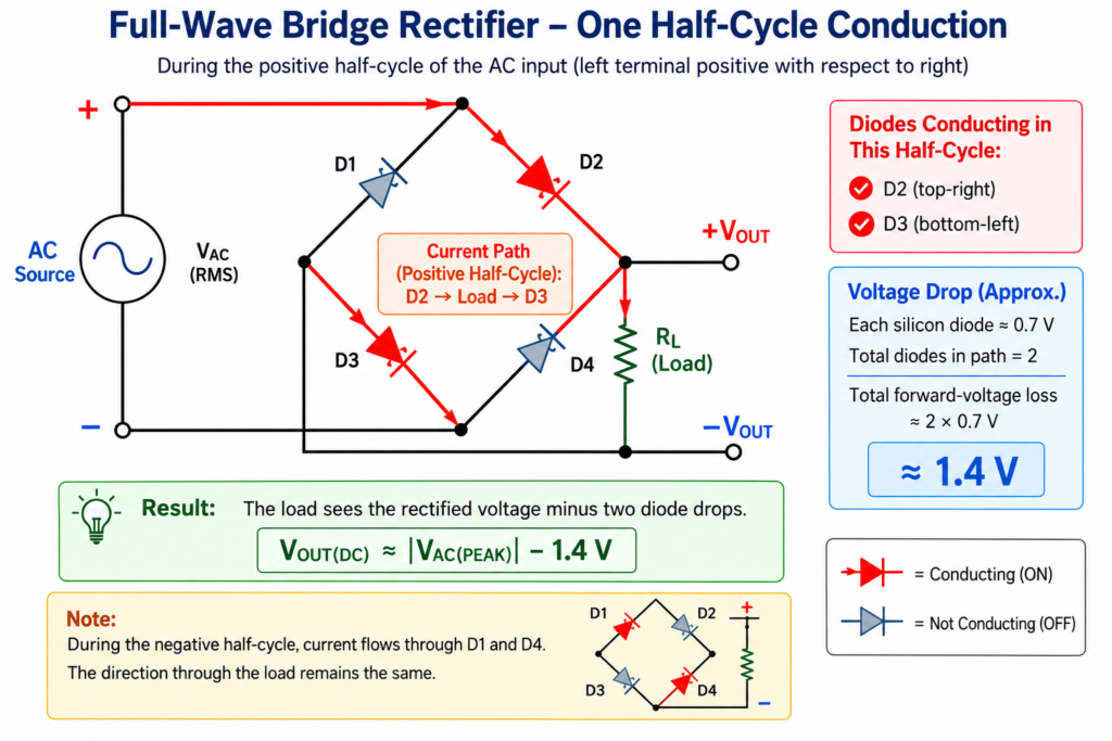
The number of diode junctions in the conducting path depends on the rectifier configuration:
- Half-wave rectifier: Current flows through one diode, so the circuit has approximately one diode voltage drop during conduction.
- Full-wave center-tapped rectifier: Only one diode conducts at a time, so there is approximately one diode voltage drop in the conducting path.
- Bridge rectifier: Current passes through two diodes during each half-cycle, resulting in approximately two diode voltage drops.
For a bridge rectifier, the total voltage loss can be approximated as:
For example, if each diode has a forward voltage of 0.7 V, the conducting path of a bridge rectifier has approximately:
Therefore, a 12 V rectifier input does not deliver the full 12 V to the load. Approximately 1.4 V is lost across the conducting diodes under the assumed operating conditions.
Diode Voltage Drop and Power Loss
The power dissipated by a conducting diode can be estimated using:
For a bridge rectifier with two conducting diodes, the approximate conduction loss is:
For example, with 0.7 V per diode and a load current of 2 A:
Thus, the two conducting diodes dissipate approximately 2.8 W as heat.
The effect becomes more significant in low-voltage and high-current power supplies. For example, a 1.4 V loss is relatively small in a 230 V rectifier system but can be a substantial percentage of the available voltage in a 5 V or 12 V supply.
This is one reason Schottky diodes, which generally have a lower diode voltage drop than conventional silicon PN diodes, are often preferred in low-voltage rectification and switching applications.
Diode Voltage Drop in Reverse Polarity Protection
A diode is commonly connected in series with a power supply to provide reverse polarity protection. When the supply polarity is correct, the diode conducts and powers the circuit. If the supply is connected backward, the diode blocks the reverse current and helps protect downstream components.
The disadvantage of this simple protection method is the diode voltage drop. During normal operation, the voltage available to the load is:
For example, if a 5 V supply passes through a silicon diode with a forward voltage of 0.7 V:
Only about 4.3 V reaches the protected circuit.
Using a Schottky diode can reduce this loss because its forward voltage is generally lower than that of a conventional silicon PN diode.
| Protection Method | Typical Voltage Loss | Main Advantage |
| Silicon diode | ~0.6–0.8 V | Simple and inexpensive |
| Schottky diode | ~0.15–0.45 V | Lower diode voltage drop |
| MOSFET-based ideal-diode circuit | Very low | Minimal conduction loss |
The actual voltage loss depends on current, temperature, and the selected component. A MOSFET-based ideal-diode arrangement does not eliminate voltage loss completely; instead, its conduction loss is primarily associated with the MOSFET’s on-resistance.
Why Diode Voltage Drop Matters in Low-Voltage Circuits
The effect of diode voltage drop becomes especially important when the supply voltage is already low. A loss of 0.7 V may be relatively insignificant in a high-voltage circuit, but it can consume a substantial portion of a 3.3 V or 5 V supply.
This is particularly important in:
- 3.3 V electronic systems
- Battery-powered devices
- IoT and sensor nodes
- USB-powered circuits
- Portable electronic equipment
For example, consider a 3.3 V supply protected by a silicon diode with a 0.7 V forward drop:
The diode consumes:
of the supply voltage.
In other words, more than one-fifth of the available supply voltage is lost across the diode. The resulting 2.6 V may even be too low for a circuit designed to operate from a 3.3 V rail.
Replacing the silicon diode with a Schottky diode having, for example, a 0.3 V forward drop would increase the available voltage to approximately:
Therefore, minimizing diode voltage drop is particularly important in low-voltage and battery-powered designs. Schottky diodes can reduce the loss, while MOSFET-based reverse-polarity protection can provide an even lower voltage loss when efficiency and available supply voltage are critical.
Conclusion
The diode voltage drop is an important parameter that determines how much voltage is lost when a diode conducts. Its value is not fixed and depends on the diode type, forward current, temperature, and device construction. As a general reference, silicon diodes are often around 0.6–0.8 V, Schottky diodes typically have a lower forward voltage, while LEDs generally have a higher forward voltage.
For quick circuit calculations, typical values such as 0.7 V for a silicon diode can be useful. However, for actual component selection and power-electronic designs, the manufacturer’s datasheet provides a more reliable at the required operating current and temperature.
The diode voltage drop also directly affects output voltage, power dissipation, rectifier efficiency, and the performance of low-voltage circuits. Measuring Vf with a multimeter in diode-test mode provides a quick way to check a diode’s forward conduction and identify common faults.
Understanding and accounting for the diode voltage drop helps ensure that the selected diode operates safely and that the circuit receives the voltage and efficiency required for reliable operation.
Read Next: