The slew rate indicates how rapidly an output voltage can change in response to a varying input signal. It is an important parameter for determining how effectively an amplifier can reproduce rapidly changing signals. The slew rate becomes particularly important when amplifying high-frequency or large-amplitude signals, because a limited slew rate can prevent the output from accurately following the required waveform and may result in distortion.
A low-slew-rate op-amp may reproduce slowly changing signals accurately but distort fast-changing signals. Understanding the op-amp slew rate, its formula, calculation, measurement, and effect on amplifier performance is therefore essential when selecting an op-amp for a practical application.
What is Slew Rate?
Slew Rate is the maximum rate at which the output voltage of an operational amplifier (op-amp) can change with time. It indicates how quickly an op-amp can respond to a changing input signal and produce the required output voltage without significant distortion.
The Slew Rate is defined as:
where SR is the slew rate and represents the rate of change of the output voltage with respect to time.
For example, an op-amp with a Slew Rate of 10 V/µs can change its output voltage at a maximum rate of approximately 10 volts in 1 microsecond under the specified operating conditions.
The Slew Rate is particularly important when an op-amp handles large or rapidly changing signals. If the required output voltage changes faster than the amplifier’s maximum slew rate, the op-amp cannot follow the input signal accurately. This can cause waveform distortion and limit the maximum usable signal amplitude or frequency.
For a particular output voltage swing, a higher signal frequency requires a higher slew rate. Therefore, the Slew Rate helps determine whether an op-amp can reproduce a high-frequency signal with the required output amplitude without significant slew-rate distortion.
The Slew Rate is a large-signal limitation of an op-amp. It differs from small-signal bandwidth, which describes the amplifier’s frequency response for relatively small signals.
Slew Rate Formula
The basic slew-rate formula is:
where:
- = slew rate
- = change in output voltage
- = time required for that voltage change
Therefore, if the output changes from to in a measured time interval:
For a rising output transition, the positive slew rate is measured. For a falling transition, the negative slew rate can be measured.
The magnitude of the two values may not always be identical in a practical op-amp, so datasheets may specify separate positive and negative slew-rate characteristics.
Slew Rate Units
The Slew Rate of an electronic circuit represents how quickly its output voltage changes with respect to time. It is therefore expressed as volts per unit of time. The commonly used units are volts per microsecond (V/µs) and volts per second (V/s).
Why Does Slew Rate Matter?
An ideal op-amp would be able to change its output voltage instantaneously. A real op-amp cannot do this because its internal circuitry has limitations on how rapidly it can charge and discharge internal capacitances.
If the required output voltage changes faster than the op-amp’s maximum slew rate, the output cannot follow the desired waveform.
For example, suppose a circuit requires the output to change by in .
The required slew rate would be:
An op-amp whose available slew rate is lower than this required value would not be able to reproduce this transition accurately.
Slew Rate of Op-Amp
The slew rate of an op-amp indicates how quickly its output voltage can respond to a change in the input signal. Therefore, it places a practical limit on the maximum frequency and amplitude of signals that the op-amp can reproduce accurately.
When the required output voltage changes faster than the op-amp’s specified slew rate, the output cannot follow the input waveform correctly. This can result in waveform distortion, particularly in high-frequency or large-amplitude signal applications.
The slew rate may also differ for positive and negative output transitions because the internal circuit configuration and current-driving capabilities of the op-amp are not necessarily identical in both directions.
An ideal op-amp would have an infinite slew rate, allowing its output to change instantaneously. In practice, every op-amp has a finite value. For example, the commonly used IC 741 op-amp has a typical slew rate of approximately 0.5 V/µs, which limits its ability to handle high-frequency, large-amplitude signals without distortion.
How to Measure Slew Rate?
The slew rate of an op-amp can be determined by applying a fast, large-amplitude step signal to its input and observing how quickly the output voltage changes. A step input of approximately 1 V is commonly used for this measurement.
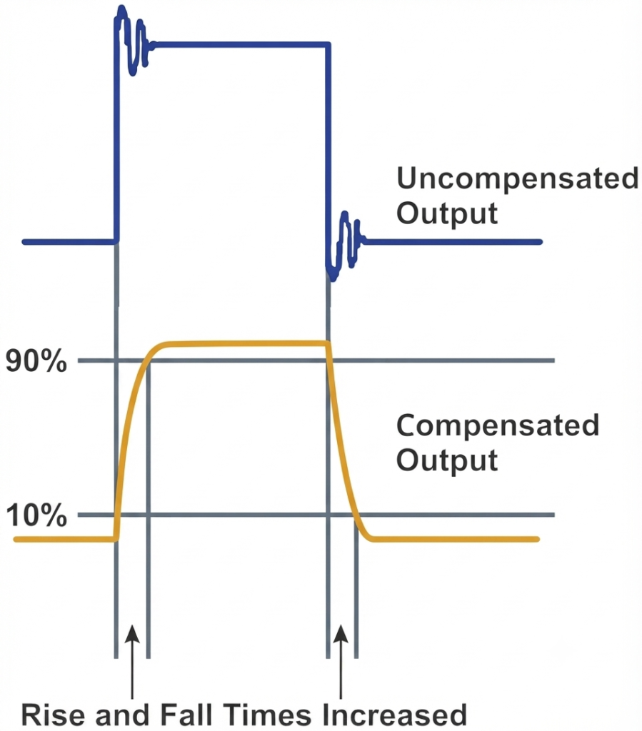
The slew rate is obtained from the output waveform by measuring the voltage change between 10% and 90% of the final output amplitude and dividing it by the corresponding time interval:
where:
- = output voltage at 90% of its final value
- = output voltage at 10% of its final value
- = time at which the output reaches 90%
- = time at which the output reaches 10%
A function generator is used to produce the step or square-wave input, while an oscilloscope is used to observe the input and output waveforms and measure the voltage rise time.
The basic setup for measuring the slew rate consists of the op-amp under test, a function generator, and an oscilloscope.
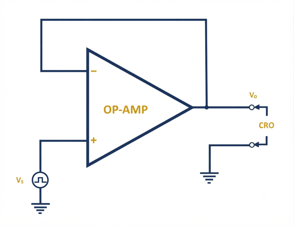
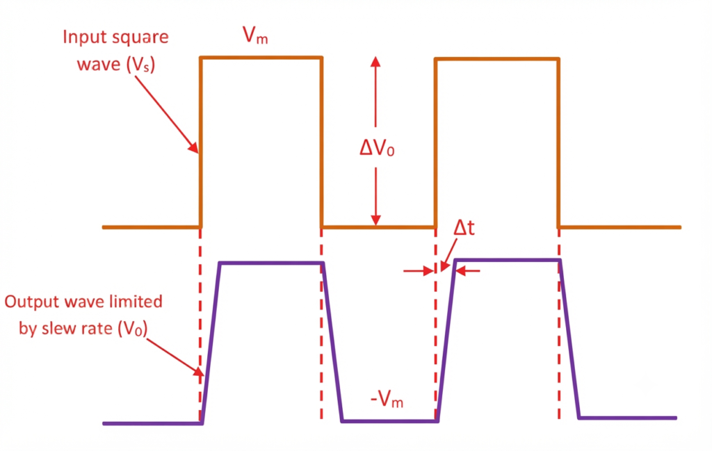
The output waveform shows the maximum rate at which the op-amp can change its output voltage when the input changes rapidly.
The typical input signal and the corresponding slew-rate-limited output waveform are shown below.
Slew Rate and Sine-Wave Signals
Slew-rate limitations are particularly important when an op-amp amplifies a high-frequency sine wave.
Consider a sinusoidal output:
where:
- = peak output voltage
- = frequency
Differentiating with respect to time gives:
The maximum value occurs when the cosine term is equal to 1. Therefore, the maximum required slew rate is:
This is one of the most useful equations when determining whether an op-amp can accurately reproduce a sinusoidal signal.
Op-Amp Slew Rate Calculation
An operational amplifier is required to amplify a sinusoidal signal having a peak voltage of 5 V at a frequency of 100 kHz. Determine the minimum slew rate required for the op-amp to reproduce the signal without distortion.
The required slew rate for a sinusoidal signal is given by:
where:
- is the peak voltage
- is the signal frequency
Substituting the given values:
Since ,
Therefore, the op-amp should have a minimum slew rate of approximately 3.14 V/µs to amplify this signal without slew-rate-induced distortion.
The table below demonstrates that the required slew rate increases directly with both output amplitude and frequency.
| Peak Output Voltage | Frequency | Required Slew Rate |
| 1 V | 10 kHz | 0.063 V/µs |
| 2 V | 20 kHz | 0.251 V/µs |
| 5 V | 50 kHz | 1.571 V/µs |
| 5 V | 100 kHz | 3.142 V/µs |
| 10 V | 100 kHz | 6.283 V/µs |
| 10 V | 500 kHz | 31.42 V/µs |
This table demonstrates that the required slew rate increases directly with both output amplitude and frequency.
Slew Rate vs Bandwidth
Slew rate and bandwidth are related but different op-amp specifications. Both determine how effectively an op-amp can handle varying signals, but they describe different limitations. Slew rate is mainly associated with large-signal performance, whereas bandwidth describes the op-amp’s small-signal frequency response.
Slew Rate
The slew rate is the maximum rate at which an op-amp can change its output voltage in response to a rapidly changing input. It is normally specified in V/µs and indicates how quickly the amplifier can respond to a large-amplitude signal.
For a sinusoidal output, the required rate of voltage change increases with both signal frequency and amplitude. If this required rate exceeds the op-amp’s slew rate, the output cannot follow the input waveform accurately. The smooth sinusoidal shape may then become distorted, with portions of the waveform appearing more linear or triangular.
Slew-rate limiting is a nonlinear, large-signal limitation and can therefore introduce waveform distortion.
Bandwidth
The bandwidth of an op-amp describes its frequency response and is generally specified in hertz (Hz). It indicates the range of frequencies over which the amplifier can provide its specified gain within defined limits.
As the input frequency increases toward and beyond the op-amp’s bandwidth, the gain decreases and the phase shift increases. The internal poles of the op-amp contribute to this frequency-dependent behavior, giving the amplifier low-pass characteristics.
Bandwidth limitation is generally treated as a linear, small-signal effect. It changes the amplitude and phase of the signal rather than producing the nonlinear waveform distortion associated with slew-rate limiting.
Comparison of Slew Rate and Bandwidth
| Parameter | Slew Rate | Bandwidth |
| Describes | Maximum output voltage rate of change | Frequency response |
| Type of limitation | Large-signal | Small-signal |
| Common unit | V/µs | Hz |
| Important for | Fast, large-amplitude signals | Frequency-dependent gain |
| Typical test | Large step or square-wave response | Small-signal frequency sweep |
| Main effect | Can cause waveform distortion | Gain reduction and phase shift |
An op-amp can have a high bandwidth and still experience slew-rate distortion when it is required to reproduce a high-frequency signal with sufficiently large amplitude. Therefore, both slew rate and bandwidth should be considered when selecting an op-amp for high-frequency or fast-changing signal applications.
Relation Between Slew Rate and Full Power Bandwidth
When the input signal is sinusoidal, the slew rate determines the highest frequency at which the op-amp can reproduce the signal without slew-rate-induced distortion. This maximum frequency is known as the full-power bandwidth of the amplifier.
Assume that the input signal is:
For a unity-gain non-inverting amplifier, the output follows the input signal, so:
To determine the maximum rate of change of the output voltage, differentiate the above equation with respect to time:
This gives:
The maximum value of occurs when:
Therefore, the maximum rate of change is:
The maximum rate of output-voltage change is equal to the slew rate (S) of the op-amp. Hence:
Since:
we can write:
where:
- = slew rate in V/s
- = maximum signal frequency in Hz
- = peak value of the output voltage in V
Rearranging the equation gives:
This equation gives the maximum frequency at which an op-amp can reproduce a sinusoidal signal of peak amplitude without slew-rate-induced distortion. This frequency is known as the full-power bandwidth (FPBW) or slew-rate-limited bandwidth.
Thus, the full-power bandwidth depends directly on the op-amp’s slew rate and inversely on the peak output voltage. A higher slew rate allows the amplifier to reproduce higher-frequency, large-amplitude signals without slew-rate distortion.
Slew Rate and Waveform Distortion
When sine waves have the same amplitude but different frequencies, their peak voltage remains unchanged; however, the rate at which the voltage changes with time increases with frequency. Therefore, a higher-frequency waveform requires a greater slew-rate capability to reproduce its shape accurately.
As the frequency or output amplitude increases, the required rate of output-voltage change also increases. When this requirement approaches the available slew rate, the output begins to lose its ability to follow the input waveform accurately. Once the required rate exceeds the available slew rate, slew-rate-induced distortion occurs.
For a sinusoidal signal, this limitation is often first noticeable around the portions of the waveform where the voltage changes most rapidly. With further increase in frequency or amplitude, the curved portions of the sine wave can become progressively more linear, giving the waveform a shape that approaches a triangular form.
The effect becomes more significant when:
- Output amplitude increases, because a larger voltage swing requires a greater rate of change.
- Signal frequency increases, because the output must complete its voltage transitions in a shorter time.
- Closed-loop gain increases the output amplitude, thereby increasing the required slew rate for a given frequency.
- The available slew rate is relatively low, making the amplifier reach its limiting condition at lower frequencies or amplitudes.
Thus, an amplifier may have adequate voltage gain and bandwidth yet still fail to reproduce a large-amplitude, high-frequency signal accurately if its slew-rate capability is insufficient.
Slew Rate and Square-Wave Signals
A square wave contains very fast voltage transitions. An op-amp with a limited slew rate cannot reproduce an ideal instantaneous transition.
Instead, the output changes at a finite rate:
For example, if the output needs to change by and the op-amp has a slew rate of , the minimum transition time is:
Thus, the output cannot make the 8-V transition faster than approximately , assuming the slew-rate limit is the controlling factor.
This is why op-amps with higher slew rates are often preferred for pulse, square-wave, switching, and high-speed signal applications.
Factors Affecting Op-Amp Slew Rate
The following factors influence the effective slew-rate performance of an op-amp.
High Gain at the Input Stage of an Op-Amp
Modern operational amplifiers use differential input stages that provide high gain and exhibit transconductance characteristics. These stages convert a differential input voltage into an output current. Transconductance, also called mutual conductance, describes the relationship between the output current and input voltage and is expressed as:
A high transconductance in the input stage contributes significantly to the large open-loop gain of an op-amp. Because of this high gain, even a relatively small differential input voltage can drive the internal stage toward saturation.
When the input stage approaches saturation, its output current becomes nearly constant and the stage behaves approximately like a constant-current source. The available current then limits how quickly the internal compensation capacitor can charge or discharge.
Since the output voltage can change only as fast as the internal capacitor is charged or discharged, this current limitation directly affects the maximum rate of output-voltage change. Consequently, the input-stage current capability and internal compensation capacitance are important factors that determine the slew rate of an op-amp.
Frequency Compensation at the Second Stage of an Op-Amp
Frequency compensation is incorporated into op-amps to improve stability and prevent unwanted high-frequency oscillations. However, the compensation network also influences the amplifier’s high-frequency response and, consequently, its slew rate.
The second stage of a compensated op-amp typically exhibits a low-pass response and can be considered similar to an integrator over the relevant operating range. When this stage receives an approximately constant current, the compensation capacitor charges at a nearly constant rate. As a result, the output voltage changes approximately linearly with time.
If the second stage has an effective capacitance and a voltage gain , the slew rate can be expressed as:
where:
- = slew rate of the op-amp
- = approximately constant current supplied by the first stage when it is in saturation
- = effective compensation capacitance
- = voltage gain of the second stage
Thus, the slew rate depends on the available charging current and the effective compensation capacitance. A higher available current increases the slew rate, whereas a larger compensation capacitance reduces the rate at which the output voltage can change.
Temperature
The slew rate of an op-amp can vary with temperature because the electrical characteristics of its internal semiconductor devices and bias circuits change as temperature changes.
The positive slew rate refers to the maximum rate of output-voltage increase during a rising transition, while the negative slew rate represents the maximum rate of output-voltage decrease during a falling transition.
For many amplifier designs, the slew rate tends to increase as temperature rises. However, the exact temperature dependence varies with the op-amp’s internal design and operating conditions. Therefore, the manufacturer’s datasheet should be consulted when precise slew-rate performance over a temperature range is required.
Internal Compensation
Most internally compensated op-amps use one or more compensation capacitors to maintain stability when negative feedback is applied. These capacitors play an important role in determining the amplifier’s frequency response.
During a rapid change in the output voltage, the internal compensation capacitor must be charged or discharged. The rate at which this occurs depends on the current available from the internal amplifier stages. If the available current is limited, the capacitor cannot charge or discharge quickly enough, restricting the rate of output-voltage change.
Therefore, the value of the compensation capacitance and the current available to charge or discharge it are important factors that influence the slew rate.
Output Amplitude
The required slew rate of an op-amp increases with the peak output voltage when amplifying a sinusoidal signal. The relationship can be expressed as:
where is the signal frequency and is the peak output voltage.
Thus, for a fixed frequency:
A larger output amplitude produces a steeper portion of the sine wave and therefore requires a higher slew rate. An op-amp that can reproduce a small-amplitude signal without distortion may show slew-rate distortion when the output amplitude is increased.
Frequency
The required slew rate also increases directly with the frequency of a sinusoidal signal. From:
for a constant output amplitude:
As frequency increases, the output voltage must change more rapidly to follow the input waveform. If the required rate exceeds the op-amp’s specified slew rate, the output waveform can become distorted.
Therefore, an op-amp may reproduce a particular signal accurately at a lower frequency but exhibit slew-rate distortion when the same signal is operated at a higher frequency.
Load
The load connected to an op-amp output can influence its dynamic performance, especially when the load is capacitive or requires significant output current.
A capacitive load requires additional current whenever the output voltage changes. The approximate relationship is:
where is the load capacitance and is the rate of output-voltage change.
Consequently, a larger capacitive load requires more output current for the same voltage-transition rate. If the op-amp cannot provide sufficient current, the output transition may slow down and the effective slew performance can be affected.
Supply Voltage
The supply voltage influences the operating conditions and available output-voltage range of an op-amp. A change in supply voltage can alter the bias currents and internal operating points, depending on the amplifier’s design.
Supply voltage also determines how close the output can typically swing toward the supply rails. This is important when a large-amplitude signal is being amplified because the required output swing must remain within the amplifier’s specified operating range.
The specified slew rate can also vary with supply voltage for some op-amps. Therefore, when evaluating slew-rate performance, the supply-voltage conditions given in the manufacturer’s datasheet should be considered rather than assuming that the nominal slew-rate value applies under every operating condition.
Rise and Fall Times of the Input Signal
The rise and fall times indicate how quickly an input signal changes between its low and high voltage levels, particularly in square waves and digital pulses. An op-amp with an insufficient slew rate may be unable to reproduce these rapid transitions accurately, resulting in slower output edges and waveform distortion. In high-speed circuits, this limitation can affect signal integrity, introduce timing errors, and reduce the reliability of data transmission.
Slew Rate of an Ideal Op-Amp
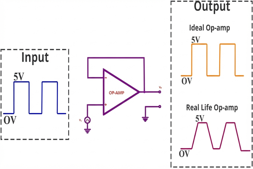
An ideal operational amplifier is assumed to have an infinite slew rate.
Therefore:
An ideal op-amp could change its output voltage instantaneously regardless of the input signal frequency or amplitude.
Real op-amps have finite slew rates because their internal circuitry cannot produce unlimited rates of voltage change.
Slew Rate of Popular Op-Amps
The following table lists the typical slew rates of several commonly used op-amps. The actual value can vary with operating conditions such as supply voltage, load, temperature, and the specific device version, so the manufacturer’s datasheet should be consulted for design work.
| Op-Amp | Typical Slew Rate (V/µs) | Typical Application / Feature |
| LM741 | 0.5 | General-purpose op-amp commonly used in basic analog and educational circuits |
| TL071 | 13 | JFET-input op-amp suitable for low-noise and audio applications |
| LM324 | 0.5 | Quad op-amp widely used in single-supply analog circuits |
| LM358 | 0.3 | Dual op-amp commonly used in low-power and single-supply applications |
| OP07 | 0.3 | Precision op-amp designed for low-offset and accurate signal amplification |
| RC4558 | 1.7 | Dual general-purpose op-amp used in analog and audio circuits |
| LM833 | 7 | Dual low-noise op-amp commonly used in audio preamplifiers and mixers |
| NE5532 | 9 | Low-noise, high-performance dual op-amp widely used in audio applications |
| TL082 | 13 | JFET-input op-amp suitable for general-purpose and higher-speed analog circuits |
| CA3140 | 9 | MOSFET-input op-amp used for signal processing and high-input-impedance applications |
| OPA2134 | 20 | High-performance FET-input op-amp designed for low-distortion audio applications |
Applications of Slew Rate
The slew rate is important in electronic systems where an output voltage must change rapidly or at a controlled rate. It becomes particularly significant when signals have high frequency, large amplitude, or fast transitions. Some common applications include:
- Audio amplifiers: Slew rate determines how accurately an amplifier can reproduce rapidly changing audio signals, particularly at higher frequencies and larger output amplitudes.
- Function and waveform generators: Slew-rate capability is important when generating high-frequency sine waves, square waves, ramps, and other rapidly changing waveforms.
- Active filters: Op-amps used in active filters must have sufficient slew rate to process signals at the required frequency and amplitude without introducing slew-induced distortion.
- Data-acquisition circuits: Signal-conditioning and buffer amplifiers in data-acquisition systems may need adequate slew rate to respond quickly to changing input signals.
- Analog signal conditioning: Amplifiers, buffers, and other conditioning circuits use op-amps to process sensor and measurement signals. Adequate slew rate helps maintain the required waveform during rapid signal changes.
- ADC and DAC buffer circuits: Buffer amplifiers associated with analog-to-digital and digital-to-analog converters may require sufficient slew rate to charge or discharge their input or output capacitances quickly.
- Pulse amplifiers: Applications involving pulses and fast transitions require amplifiers capable of changing their output voltage rapidly without excessive slew-rate limitation.
- High-speed instrumentation: Measurement and instrumentation circuits handling rapidly varying signals require appropriate slew-rate capability to reproduce signal changes accurately.
- Motor-control signal circuits: Slew-rate control can be used to make control-voltage transitions gradual, helping provide smoother changes in control signals. In some systems, software-based slew functions or dedicated slew circuitry are used for this purpose.
- Communication circuits: High-speed communication signals can contain rapid voltage transitions, making slew-rate capability an important consideration in suitable analog interface and amplification stages.
- Musical instruments: In electronic musical instruments and synthesizers, slew circuitry can gradually transition a control voltage from one level to another. This produces effects such as portamento, glide, or lag, creating a smooth transition between notes.
- Control systems: Slew-rate limiting is used when a control voltage should not change instantaneously. Instead, the voltage is allowed to move gradually toward its new value over a specified period.
In low-frequency and small-amplitude applications, the required slew rate may be relatively low and therefore may not be the primary performance limitation. In contrast, high-frequency signals with large output amplitudes require a much higher slew rate. If the required rate of output-voltage change exceeds the op-amp’s specified slew rate, the output waveform can become distorted.
Conclusion
The slew rate of an op-amp specifies the maximum rate at which its output voltage can change and is normally expressed in V/µs. It is a key large-signal parameter that determines whether an op-amp can accurately reproduce rapidly changing signals.
The basic slew-rate formula is:
For a sinusoidal output, the required slew rate is:
As frequency or output amplitude increases, the required slew rate also increases. If the required value exceeds the op-amp’s available slew rate, the output waveform can become distorted. Therefore, slew rate, bandwidth, output swing, and load requirements should all be considered when selecting an op-amp for a particular application.
Read Next:
- Inverting vs Non-Inverting Amplifier: Differences, Gain, and Applications
- Inverting Operational Amplifier: Circuit, Working, and Gain Formula
- Op-Amp Building Blocks: Basic Circuits and Applications
- Operational Amplifier (Op-Amp): Basics, Types, Working & Applications
- Non-inverting Operational Amplifier: Circuit, Gain & Formula
- Summing Amplifier: Circuit, Gain Formula, Derivation & Applications
- Differential Amplifier: Circuit, Types, Formula & Applications
- Op-Amp Integrator Amplifier: Formula, Working & Applications
- Op-Amp Differentiator Amplifier: Circuit, Working, Formula & Applications
- Op-Amp Multivibrator: Working, Circuit, Types & Applications
- Op-Amp Comparator: Circuit, Working, Formula, Hysteresis & Applications
- Op-Amp Monostable Multivibrator: Circuit, Working, Formula & Timing
- Passive Averager: Circuit, Equation & Op-Amp Averager
- Instrumentation Amplifier: Circuit, Working. Gain, Applications
- Transimpedance Amplifier: Circuit, Formula & Applications
- CMRR of Op-Amp: Formula, Definition, Measurement, Applications