Turn-on voltage of a diode refers to the forward voltage at which a diode begins to conduct appreciable current when forward-biased. It describes the voltage drop across the diode during conduction and is an important parameter in rectifier circuits, electronic switches, signal-processing systems, and power supplies.
A diode is a semiconductor component that primarily allows conventional current to flow from its anode to its cathode under forward bias. The voltage required to produce a particular forward current depends on the diode’s construction, semiconductor material, temperature, and operating conditions.
How Does the Diode Turn-On Voltage Develop?
The operating principle of a conventional diode is based on a PN junction formed by joining p-type and n-type semiconductor materials. When these materials are brought together, electrons and holes recombine near the junction, creating a depletion region. This region contains very few mobile charge carriers and establishes an internal electric field that opposes further carrier movement.
Applying a forward voltage reduces the potential barrier across the junction, allowing charge carriers to cross more readily. As the applied voltage increases, the forward current rises. The diode does not switch on at one perfectly defined voltage; instead, its current increases gradually and then rises rapidly over a relatively narrow voltage range.
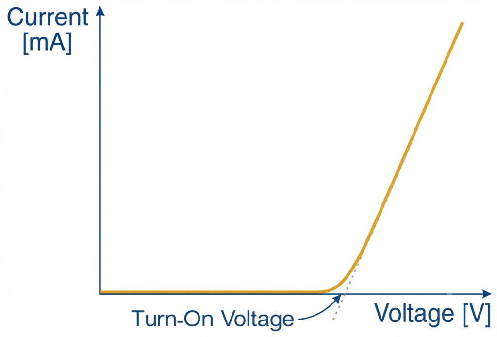
The region where the current starts increasing significantly is commonly called the knee voltage or cut-in voltage. Below this region, the forward current may be small, while above it, a modest increase in voltage can produce a substantial increase in current.
Unlike an ideal switch, a practical diode has a voltage drop during conduction. Its forward voltage depends on the current flowing through it, so the value specified in a datasheet should always be considered at the stated operating conditions.
Turn-On Voltage Values of Different Types of Diodes
The forward voltage varies among diode types because of differences in semiconductor materials and junction construction. The following table gives typical approximate values.
| Diode Type | Typical Forward Voltage |
| Silicon diode | 0.6–0.7 V |
| Germanium diode | 0.2–0.3 V |
| Schottky diode | 0.15–0.45 V |
| Red LED | 1.8–2.2 V |
| Blue LED | 3.0–3.6 V |
| White LED | 3.0–3.6 V |
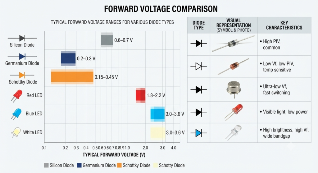
Actual values depend on the individual component, forward current, and junction temperature.
Silicon Diode
Silicon diodes are commonly used in electronic and electrical circuits because of their reliability and general-purpose performance. Their forward voltage is often approximately 0.7 V under typical operating conditions. Applications include AC-to-DC rectification, reverse-polarity protection, and signal switching.
Germanium Diode
Germanium diodes generally have a lower forward voltage than silicon diodes, typically around 0.3 V. This characteristic can be useful in low-level signal circuits. However, their comparatively higher leakage current limits their suitability for some applications.
Schottky Diode
A Schottky diode uses a metal-semiconductor junction rather than a conventional PN junction. Its relatively low forward voltage helps reduce conduction losses, making it useful in switching power supplies, DC converters, and high-frequency circuits.
Light-Emitting Diode (LED)
An LED produces light when current passes through its semiconductor junction. Its forward voltage depends largely on the semiconductor composition and the wavelength of the emitted light. Red LEDs generally have a lower forward voltage than blue and white LEDs, which typically require a higher voltage to operate.
Factors Affecting the Forward Voltage V
The forward voltage of a diode is not constant under all conditions. Two important factors that influence its value are junction temperature and forward current.
1. Effect of Temperature
For a typical silicon PN-junction diode operating at a constant current, the forward voltage decreases as the junction temperature rises. A commonly used approximation is a negative temperature coefficient of about , although the actual coefficient depends on the device and operating point.
For example, consider a silicon diode with a forward voltage of 0.70 V at 25°C. If its junction temperature rises by 40°C, the approximate change in forward voltage is:
The estimated forward voltage becomes:
This is an approximation rather than a guaranteed value. Designers must account for temperature variations when using diodes in biasing, sensing, and temperature-sensitive circuits.
2. Effect of Forward Current
The forward voltage generally increases when the current through a diode increases. Over a suitable operating range, the current-voltage relationship of a PN junction is approximately exponential.
For an idealized diode at room temperature, increasing the forward current by a factor of ten can increase the junction voltage by approximately 60 mV. Real devices may behave differently because of their construction, current level, and internal resistance.
At higher currents, the resistance of the semiconductor material and electrical contacts contributes additional voltage drop. Therefore, a diode’s forward voltage should be evaluated at the expected operating current rather than treated as a fixed value.
Importance of Forward Voltage in Circuit Design
The forward voltage affects power consumption, heat generation, rectifier output voltage, and the selection of components. Understanding its role helps engineers design efficient and reliable electronic systems.
Power Dissipation in a Diode
When current flows through a forward-biased diode, electrical power is dissipated within the component. The approximate conduction power is calculated using:
Where:
- is the power dissipated by the diode in watts.
- is the forward voltage in volts.
- is the forward current in amperes.
For example, if a diode has a forward voltage of 0.7 V and carries 2 A of current, its conduction power loss is:
The resulting heat must be managed within the component’s thermal limits. Excessive junction temperature can affect reliability and may damage the diode.
Improving Circuit Efficiency
In high-current applications, a lower forward voltage can reduce conduction losses. Schottky diodes are often used for this purpose in power converters and low-voltage circuits. However, reverse leakage current, maximum reverse voltage, switching performance, and thermal characteristics must also be considered during component selection.
Effect on Rectifier Output Voltage
In a rectifier circuit, the forward voltage reduces the voltage available to the load. A single-diode rectifier has approximately one conducting diode drop in the current path, while a conventional bridge rectifier typically has two forward-biased diodes in series at any given time.
This voltage loss influences the DC output level and contributes to power dissipation, particularly in low-voltage power supplies.
Voltage Clamping and Biasing
Diodes can also provide approximate voltage drops in biasing and clamping circuits. For instance, several silicon diodes connected in series can produce a combined forward voltage drop under a specified current.
However, a forward-biased diode is not a precision voltage reference because its voltage changes with current and temperature. For accurate voltage regulation, a dedicated reference or regulator circuit is generally more suitable.
Conclusion
The turn-on voltage of a diode describes the forward voltage associated with the onset of significant conduction. Its value depends on the diode type, forward current, and junction temperature. Silicon diodes typically operate around 0.7 V, whereas Schottky and germanium diodes generally have lower forward voltage drops.
Knowing how affects conduction, power dissipation, and output voltage helps engineers choose appropriate diodes for rectification, switching, protection, and other electronic applications.
Read Next: